
Hybrid motorcycle

a hybrid motorcycle and drive unit technology, applied in the direction of crankshaft transmission, transmission, friction roller based transmission, etc., can solve the problems of small vehicle width, disadvantageous projection of the drive unit in the vehicle width direction, and inability to provide a hybrid-type drive unit easily on a motorcycl

Active Publication Date: 2007-11-08
YAMAHA MOTOR CO LTD
View PDF1 Cites 17 Cited by
  • Summary
  • Abstract
  • Description
  • Claims
  • Application Information

AI Technical Summary

Benefits of technology

[0008] In accordance with one aspect of the present invention, a hybrid two-wheeled vehicle is provided, comprising an engine comprising a crank shaft extending in a direction generally transverse to a longitudinal axis of the motorcycle, and a generator configured to generate electric power upon rotation of the crank shaft of the engine. The vehicle also comprises an electric motor driven by at least the electric power generated by the generator, the motor configured to rotate a drive wheel via at least a reduction device and a drive-wheel transmission device, and a power distributing device configured to distribute a crank shaft drive force generated by the engine to at least the generator and the reduction device. The generator, the motor, and the power distributing device are arranged on an axis that is rearwardly spaced from and generally parallel to the crank shaft, and are disposed such that the power distributing device is positioned between the generator and the motor, the reduction device being arranged rearwardly of the power distributing device, and a front end of the drive-wheel transmission device being journaled on a reduction device storage casing that receiv

Problems solved by technology

However, such a hybrid-type drive unit cannot easily be provided on a motorcycle, which has a small vehicle width.
Additionally, when the hybrid-type drive unit is provided on a motorcycle, the drive unit disadvantageously projects considerably in a vehicle width direction from the vehicle body, affecting, for example, the weight distribution and aerodynamics of the motorcycle.

Method used


Image

  • Hybrid motorcycle
  • Hybrid motorcycle
  • Hybrid motorcycle

Examples


Embodiment Construction

[0025] In the following detailed description, terms of orientation such as “right,”“left,”“front,”“rear,”“frontward,” and “rearward” are used herein to simplify the description of the context of the illustrated embodiments. Moreover, left, right, front and rear directions are described hereinbelow as directions as seen from a driver seated on a seat of a vehicle, such as a motorcycle. Likewise, terms of sequence, such as “first” and “second,” are used to simplify the description of the illustrated embodiments. Because other orientations and sequences are possible, however, the present invention should not be limited to the illustrated orientation. Those skilled in the art will appreciate that other orientations of the various components described above are possible.

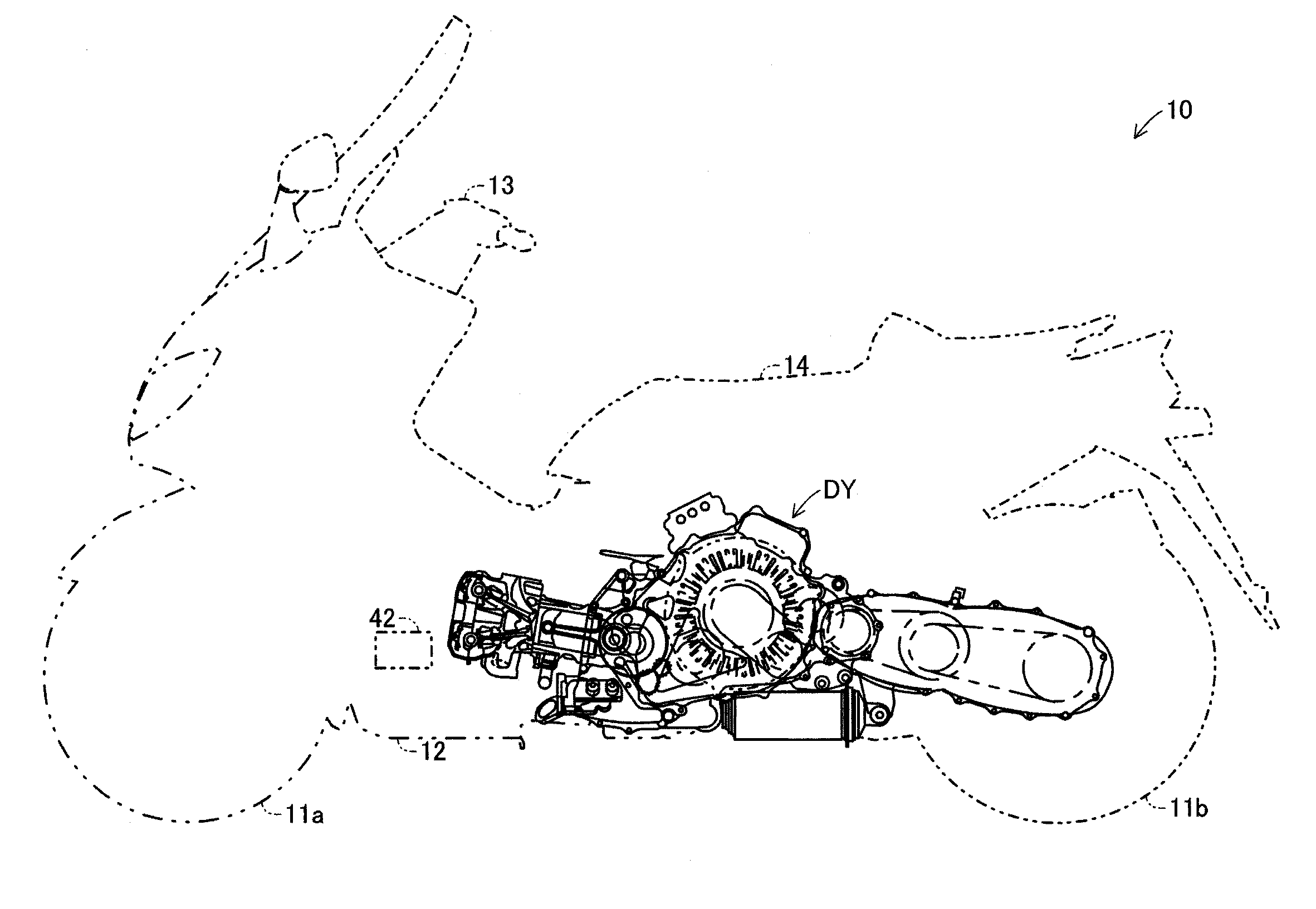
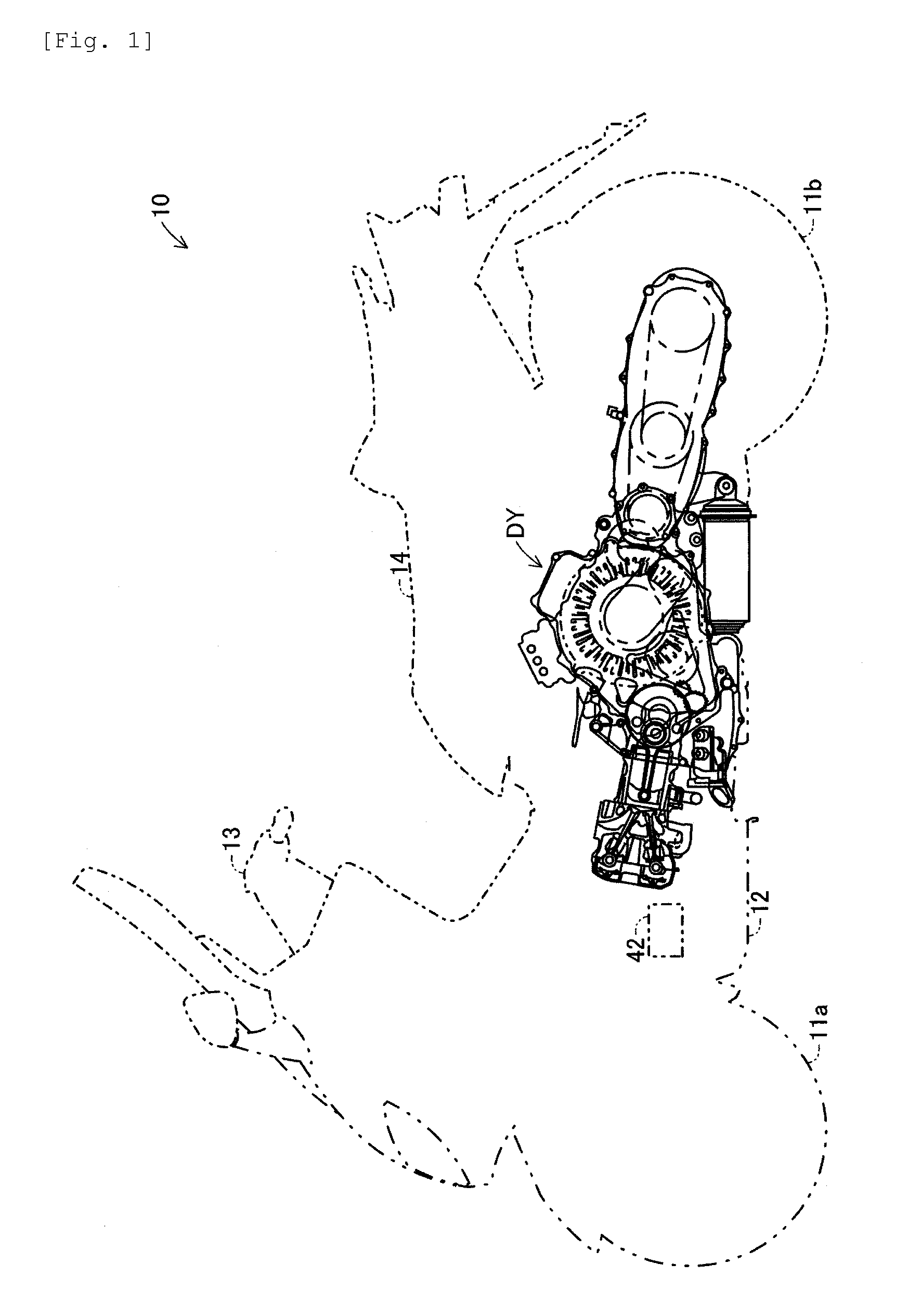
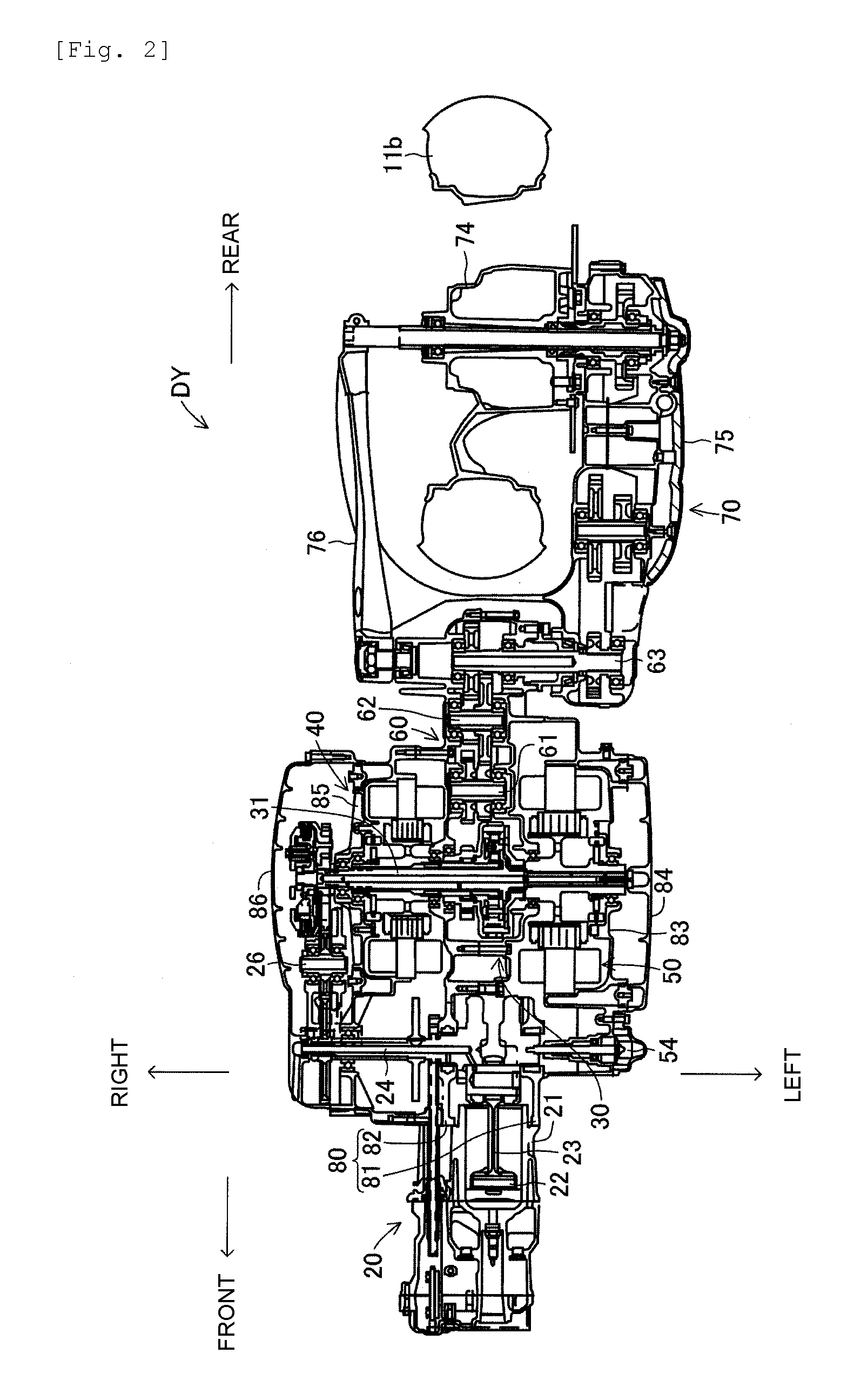
[0026]FIG. 1 shows one embodiment of a hybrid motorcycle 10 and FIG. 2 shows one embodiment of a hybrid type drive unit DY, which can be used with the hybrid motorcycle 10. The hybrid motorcycle 10 comprises a front whee...


PUM


Abstract

A hybrid motorcycle capable of mounting thereon a hybrid-type drive unit, which does not project in a vehicle width direction and can be mounted even on a motorcycle having a limited vehicle width, includes a power distributing device positioned between a generator and a motor, and a reduction device arranged rearwardly of the power distributing device. A front end of a drive-wheel transmission device is journaled on a rear end of a central storage casing so that a rear end side of the drive-wheel transmission device is vertically swingable, and a rear wheel is journaled on the rear end of the drive-wheel transmission device. The power distributing device includes a sun gear, planetary gears, a planetary carrier, and a ring gear. Further, a carrier shaft projects from a rotor shaft and rotation of a crank shaft is transmitted through a intermediate gear portion to the projecting end of the carrier shaft.

Description

CROSS-REFERENCE TO RELATED APPLICATIONS [0001] The present application is based on and claims priority under 35 U.S.C. § 119 to Japanese Patent Application No. 2006-038558, filed on Feb. 15, 2006, the entire contents of which are expressly incorporated by reference herein. BACKGROUND OF THE INVENTION [0002] 1. Field of the Invention [0003] The present invention relates to a hybrid motorcycle propelled by an engine and an electric motor. [0004] 2. Description of the Related Art [0005] While conventional vehicles generally operate by driving the rotation of a wheel or wheels via an engine, hybrid vehicles (see, for example, JP 2000-343964) utilize a drive motor in addition to an engine to operate. Such a hybrid vehicle includes an engine with an output shaft, a drive shaft, to which power output from the engine is transmitted through a power regulator, a generator having a rotating shaft, and a switching mechanism, which switches and joins the rotating shaft of the generator to the ou...

Claims


Application Information

Patent Timeline
IPC IPC(8): B60K6/02B60K6/24B60K6/26B60K6/36B60K6/365B60K6/40B60K6/405B60K6/445B60K17/04B60L50/16B62M7/02B62M11/02B62M11/14B62M23/02
CPCB60K1/02B60K6/365B60K6/405B60K6/445B60L11/14Y02T10/70B60Y2200/12B60Y2200/126Y02T10/7077Y02T10/6239Y10S903/906B60L2200/12B60L50/16Y02T10/62Y02T10/7072
Inventor MASUDA, TATSUYUKIFUKUDOME, TOSHINORISASAMOTO, SHINJI
Owner YAMAHA MOTOR CO LTD
Learn More