
Method of Establishing Belt Pullout in an Occupant Restraint System for Vehicles and an Occupant Restraint System for Vehicles

a technology for occupant restraint systems and vehicles, which is applied in the direction of pedestrian/occupant safety arrangements, vehicular safety arrangments, safety belts, etc., can solve the problem and achieve the effect of limited loading on vehicle occupants in the event of an acciden

Active Publication Date: 2007-11-08
VOLKSWAGEN AG
View PDF12 Cites 0 Cited by
  • Summary
  • Abstract
  • Description
  • Claims
  • Application Information

AI Technical Summary

Benefits of technology

[0015] The acceleration which a belt in accordance with the state of the art causes with predetermined force limitation in relation to the vehicle occupant depends on the body weight of the occupant. With a given force acting on the vehicle occupant, the acceleration of the occupant is obtained by dividing the force exerted by the belt and possibly other restraint systems on the occupant, by the body weight of the occupant. The lower the body weight of the occupant, the correspondingly higher in that respect is the acceleration caused by the force. In other words, the 5%-er female will experience a markedly higher level of acceleration than the 50%-er male, with a given force being transmitted by the belt. If now belt pullout is established by a force-travel relationship in which for example there is no belt pullout before the force transmitted by the belt exceeds 4 kN, then the 50%-er, at 4 kN, still experiences a considerable degree of acceleration while the acceleration for the 5%-er female exceeds the limit of what is tolerable. In contrast the method according to the invention ensures that, irrespective of the body weights of the occupants, the acceleration transmitted to the respective occupant can be kept within tolerable values. That can be achieved for example by belt pullout occurring only when the detected vehicle acceleration exceeds a predetermined acceleration value. The vehicle acceleration is then transmitted to the occupant to be restrained, only up to the predetermined acceleration value.
[0017] Particularly if the predetermined acceleration value represents the maximum vehicle acceleration which is to be passed on to the vehicle occupant to be restrained, the predetermined acceleration value should not exceed 60-times acceleration due to gravity (60 g). If the difference between the detected vehicle acceleration and the predetermined acceleration value is to be passed on in part to the vehicle occupant to be restrained, it is advantageous if the predetermined acceleration value is less than 60 g and preferably less than about 35 g.

Problems solved by technology

If now belt pullout is established in dependence on the detected vehicle acceleration instead of belt force, the acceleration transmitted to a vehicle occupant and thus the loading on the vehicle occupant can be limited in an accident.

Method used


Image

  • Method of Establishing Belt Pullout in an Occupant Restraint System for Vehicles and an Occupant Restraint System for Vehicles
  • Method of Establishing Belt Pullout in an Occupant Restraint System for Vehicles and an Occupant Restraint System for Vehicles
  • Method of Establishing Belt Pullout in an Occupant Restraint System for Vehicles and an Occupant Restraint System for Vehicles

Examples


Embodiment Construction

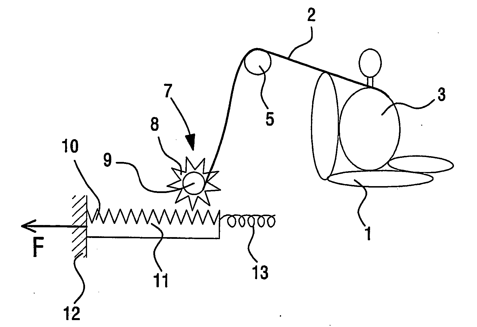
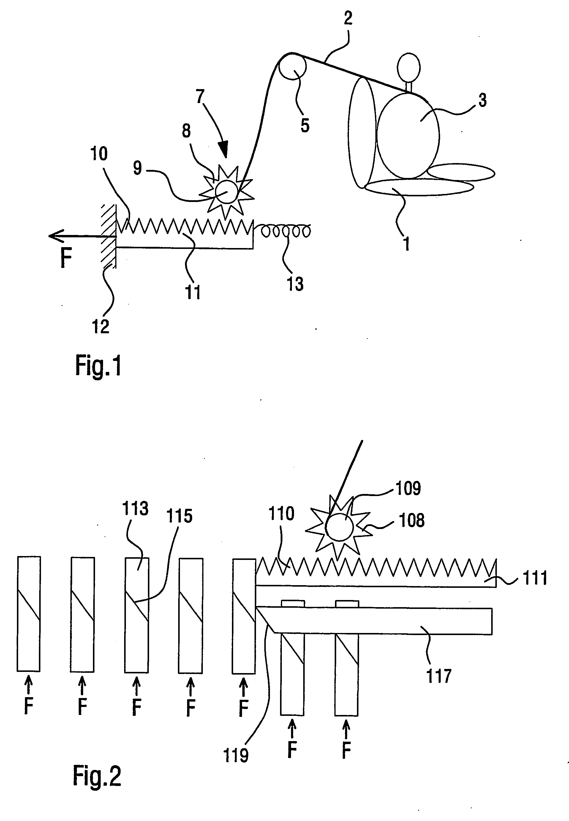
[0026] A highly diagrammatic view of an embodiment of the occupant restraint system according to the invention is shown in FIG. 1. FIG. 1 shows a vehicle seat 1, a restraint or safety belt 2 and a vehicle occupant 3 sitting on the vehicle seat 1, with the safety belt 2 fitted. The safety belt 2 is designed in such a way that, in the event of an accident, it is firstly tensioned and locked in order to hold the vehicle occupant 3 back in the seat. That prevents the occupant 3 being displaced forwardly in a direction towards the vehicle dashboard (not shown). Furthermore under given conditions the belt 2 allows belt pullout in order to prevent injury to the vehicle occupant 3 by the safety belt.

[0027] The safety belt 2 is deflected in a direction towards a blocking and release unit by way of a deflection device which is arranged in or at the B-pillar of the vehicle and which for example can be in the form of a deflection roller or deflection stirrup.

[0028] The blocking and release un...


PUM


Abstract

A method of establishing belt pullout in an occupant restraint system for vehicles with a safety belt includes the steps: detecting the vehicle acceleration, and establishing the belt pullout in dependence on the detected vehicle acceleration.

Description

BACKGROUND OF THE INVENTION [0001] 1. Field of the Invention [0002] The present invention concerns a method of establishing belt pullout in an occupant restraint system for vehicles and an occupant restraint system for vehicles. [0003] 2. Description of the Related Art [0004] Modern motor vehicles are equipped with a series of active and passive safety systems. In that respect active safety systems intervene directly in the driving characteristics of the vehicle while passive safety systems are intended to ensure protection for the occupants from injury in the event of an accident. Active safety systems are for example the anti-locking system for brakes or electronic driving dynamics regulation. Passive safety systems include for example vehicle zones which in the event of an accident are subject to defined deformation (so-called crumple zones). An important group of passive safety systems is represented by the occupant restraint systems. They provide for minimising the risk of inju...

Claims


Application Information

Patent Timeline
Patent Type & Authority Applications(United States)
IPC IPC(8): B60R21/00B65H75/48B60R22/34
CPCB60R22/28B60R2022/288B60R22/3413B60R22/322
Inventor DRAMLITSCH, THOMAS
Owner VOLKSWAGEN AG
Learn More