Printer with Embroidering Function

a printing machine and function technology, applied in printing, automatic machines, instruments, etc., can solve the problems of not being able to solve such problems, and doubts as to the capability of executing satisfactory maintenance operations, and achieve the effect of reliably and without increasing the overall siz

Inactive Publication Date: 2007-11-08
BROTHER KOGYO KK
View PDF2 Cites 10 Cited by
  • Summary
  • Abstract
  • Description
  • Claims
  • Application Information

AI Technical Summary

Benefits of technology

[0008] An object of the present invention is to provide a printer with embroidering function having features that enabling both workpiece sewing and workpiece printing without having to rearrange the hold of the workpiece cloth by the cloth holding frame; provide a print head maintenance mechanism that enables execution of maintenance operation while executing a print operation; and adapt the embroidery sewing machine for household use without increasing the overall size.
[0009] A printer with embroidering function of the present invention includes a sewing machine body capable of sewing a workpiece cloth, a cloth holding frame holding the workpiece cloth to be sewn, a frame drive unit having the cloth holding frame connected therewith to move the cloth holding frame independently in two mutually perpendicular directions on a horizontal plane, the printer with embroidering function having an ink-jet printer capable of printing the workpiece cloth of the cloth holding frame moved by the frame drive unit comprising a purging mechanism capable of purging a print head of the printing unit; a carrier mechanism characterized by being capable of switching the purging mechanism or the print head between a purging position capable of purging the print head and a printable position spaced from the purging position and capable of printing by relatively moving the purging mechanism or the print head in a horizontal direction.
[0010] According to the above construction, the provision of the sewing machine body capable of sewing the workpiece cloth; the cloth holding frame that holds the workpiece cloth to be sewn; the frame drive unit that has the cloth holding frame connected therewith to move the cloth holding frame independently in two perpendicular directions in the horizontal plane; and the ink-jet printing unit capable of printing the workpiece cloth of the cloth holding frame moved by the frame drive unit enables both sewing and printing of the workpiece cloth without having to rearrange the hold of the workpiece cloth by the cloth holding frame. Also, the above construction allows the cloth held by the cloth holding frame to be held in a consistent manner during the printing and embroidering process, thereby maintaining proper positioning between the associated sewing and printing patterns. Also, provision of the purging mechanism that performs purging operation on the print head, and a carrier mechanism capable of switching the purging mechanism or the print head between the purging position capable of purging the purging mechanism or the print head and a printable position spaced from the purging position and allowing execution of print operation by relative movement of the purging mechanism and the print head in the horizontal direction allows the purging mechanism or the print head to be reliably switched to the purging position, thereby allowing purging of the print head and reliably remove debris and dust from the nozzles of the print head.

Problems solved by technology

However, the embroidery sewing machines described in the aforementioned patent documents 1 and 2 do not disclose any means of maintenance operations, hence may be doubtful as to the capability of executing satisfactory maintenance operations.
However no such problems are addressed in the disclosures.

Method used


Image

  • Printer with Embroidering Function
  • Printer with Embroidering Function
  • Printer with Embroidering Function

Examples


first embodiment

[0035] FIGS. 1 to 9 illustrate the present invention.

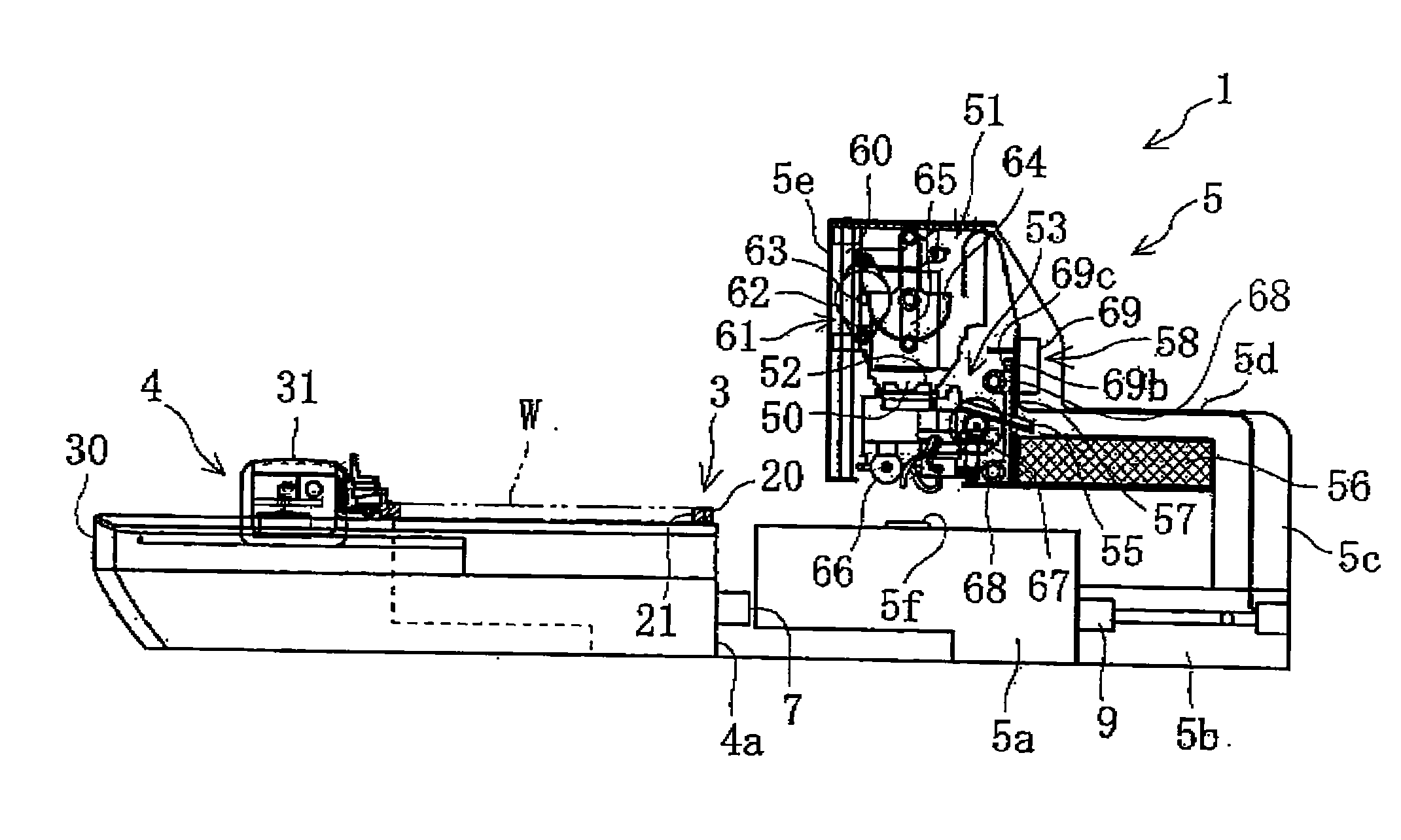
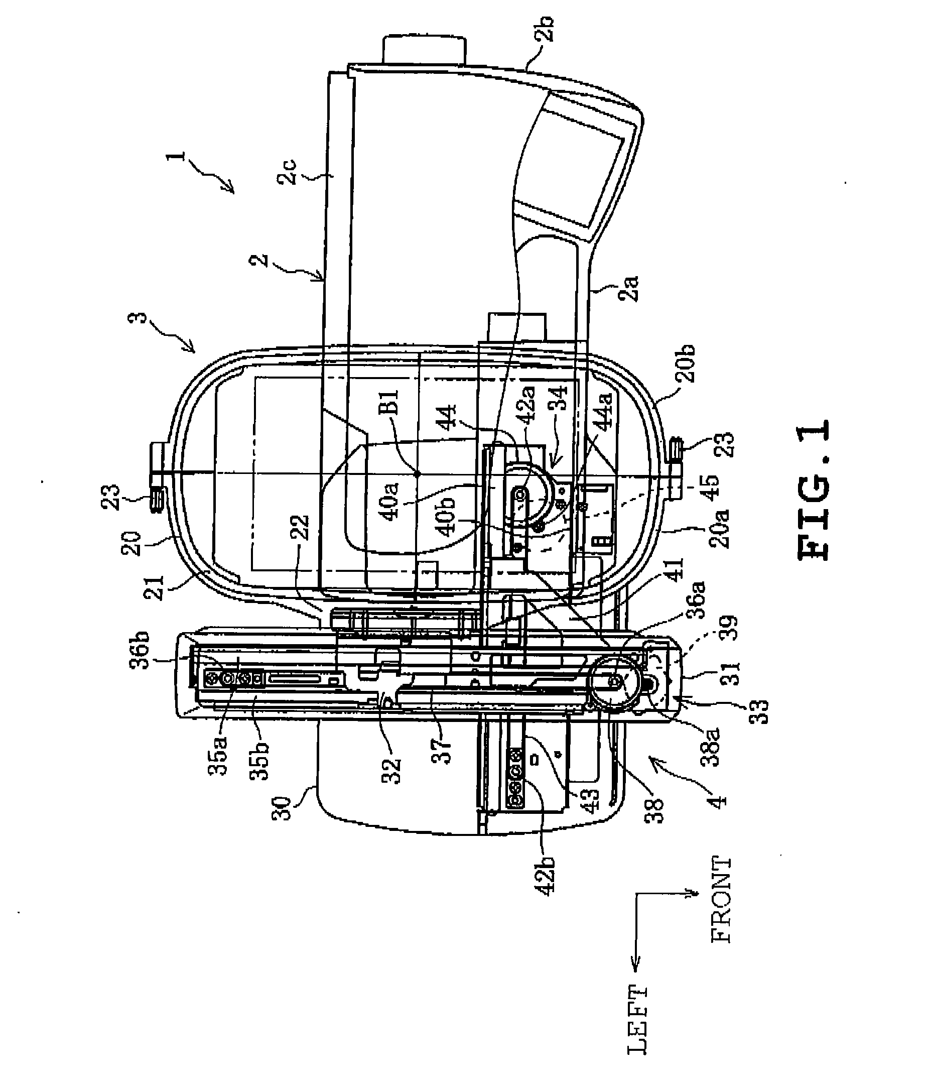
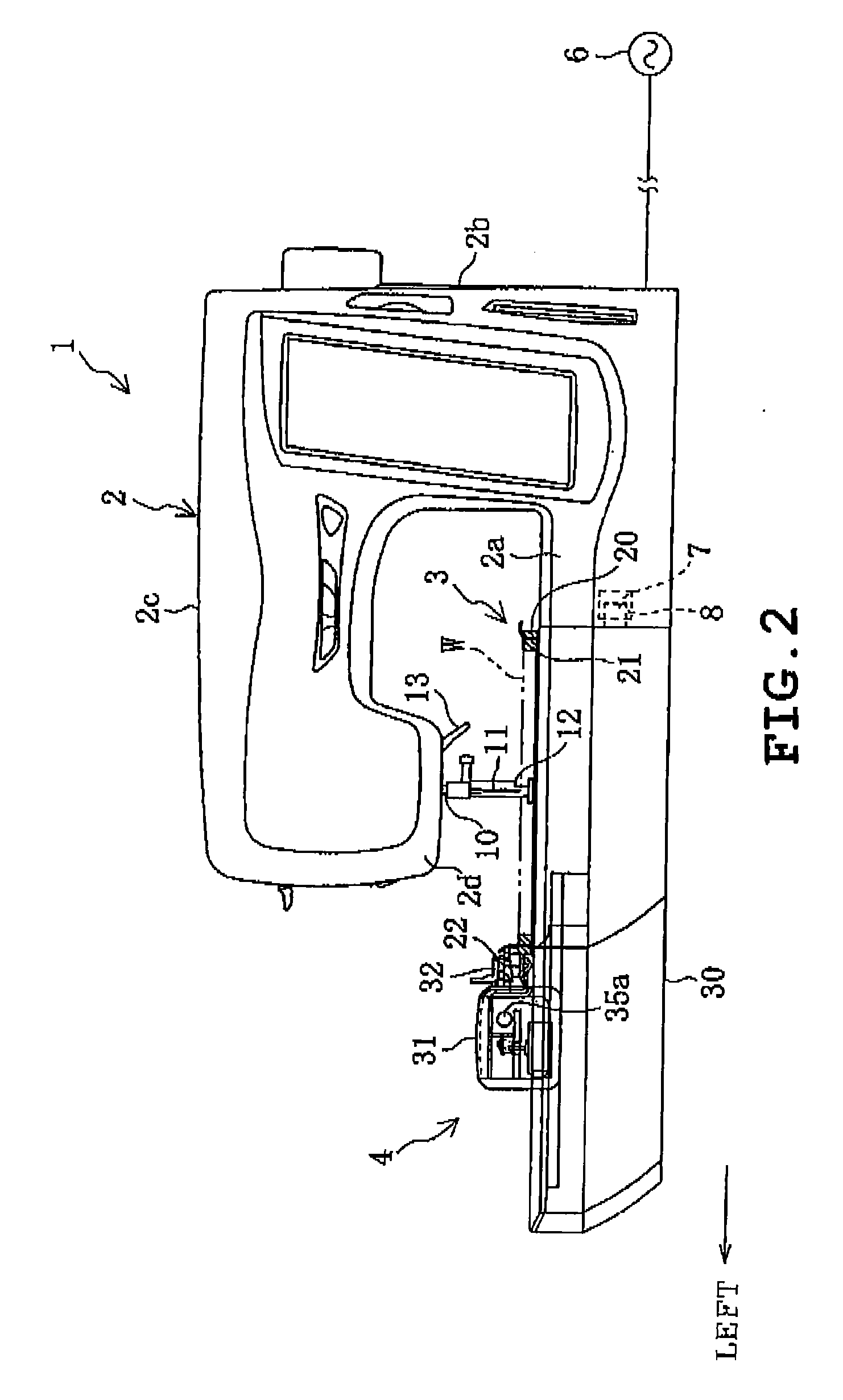
[0036] A printer with embroidering function, as shown in FIGS. 1 and 2, includes a sewing machine body 2 capable of sewing a workpiece cloth W, a cloth holding frame 3 that holds the workpiece cloth to be sewn, a frame drive unit 4 that moves cloth holding frame 3 in two perpendicular directions in a horizontal plane, and an ink-jet printing unit 5(refer to FIGS. 3 to 8). The frame drive unit 4 has an attachment portion 4a detachably attached to the sewing machine body 2, and establishes connection with the cloth holding frame 3 to move the same independently in the longitudinal and lateral directions (two perpendicular directions in the horizontal plane). The printing unit 5, as shown in FIGS. 3 to 8, is detachably attached to the attachment portion 4a of the frame drive unit 4 separated from the sewing machine body 2, and is capable of printing the workpiece cloth W of the cloth holding frame 3 being moved by the frame drive uni...


PUM


Abstract

A printer with embroidering function includes a sewing machine body 2 capable of sewing a workpiece cloth W, a cloth holding frame 3 that holds the workpiece cloth W to be sewn, a frame drive unit 4 having the cloth holding frame 3 connected therewith to move the cloth holding frame 3 independently in two perpendicular directions in a horizontal plane, the printer with embroidering function further including an ink-jet printing unit detachably a tached to an attachment portion 4a of the frame drive unit 4 separated from the sewing machine body 2 capable of printing the workpiece cloth W of the cloth holding frame 3 moved by the frame drive unit 4 and a head cap 52, a purging mechanism 53, a nozzle wiper 54, an ink receptacle 55 and a waste-ink absorbing felt 56.

Description

TECHNICAL FIELD [0001] The present invention is directed to a printer with embroidering function having a sewing machine body, a cloth holding frame, a frame drive unit, and an ink-jet printing unit. BACKGROUND ART [0002] Conventionally, an embroidery sewing machine includes a sewing machine body including a sewing needle capable of sewing a workpiece cloth, a needle bar, a needle bar vertical drive mechanism, a loop taker mechanism; a cloth holding frame that stretches and holds a workpiece cloth to be sewn; and a frame drive unit having the cloth holding frame connected therewith and driving the cloth holding frame independently in two perpendicular directions in a horizontal plane. In a household embroidery sewing machine, the frame drive unit is attached to a bed of the sewing machine body. [0003] It has been conventionally conceived to mount an ink-jet printer to the embroidery sewing machine. In such case, a print head of the printing unit is positioned in the proximity of the...

Claims


Application Information

Patent Timeline
Patent Type & Authority Applications(United States)
IPC IPC(8): B41J2/165B41J2/01B41J2/18B41J3/407B41J3/44B41J29/00D05B21/00D05B39/00D05C7/02
CPCB41J2/16517B41J3/4078D05C7/02B41J2002/1742D05B21/00B41J3/44
Inventor OGAWA, MASAOKITAZAWA, HIROSHI
Owner BROTHER KOGYO KK
Why Eureka
Try Eureka