
Network system, node, node control program, and network control method

a network control and node technology, applied in the field of network systems, can solve problems such as frame transfer failure, cut-off of possible failures different from the above-described down of master nodes, and failure to execute frame transfers

Inactive Publication Date: 2007-11-08
NEC CORP
View PDF2 Cites 51 Cited by
  • Summary
  • Abstract
  • Description
  • Claims
  • Application Information

AI Technical Summary

Benefits of technology

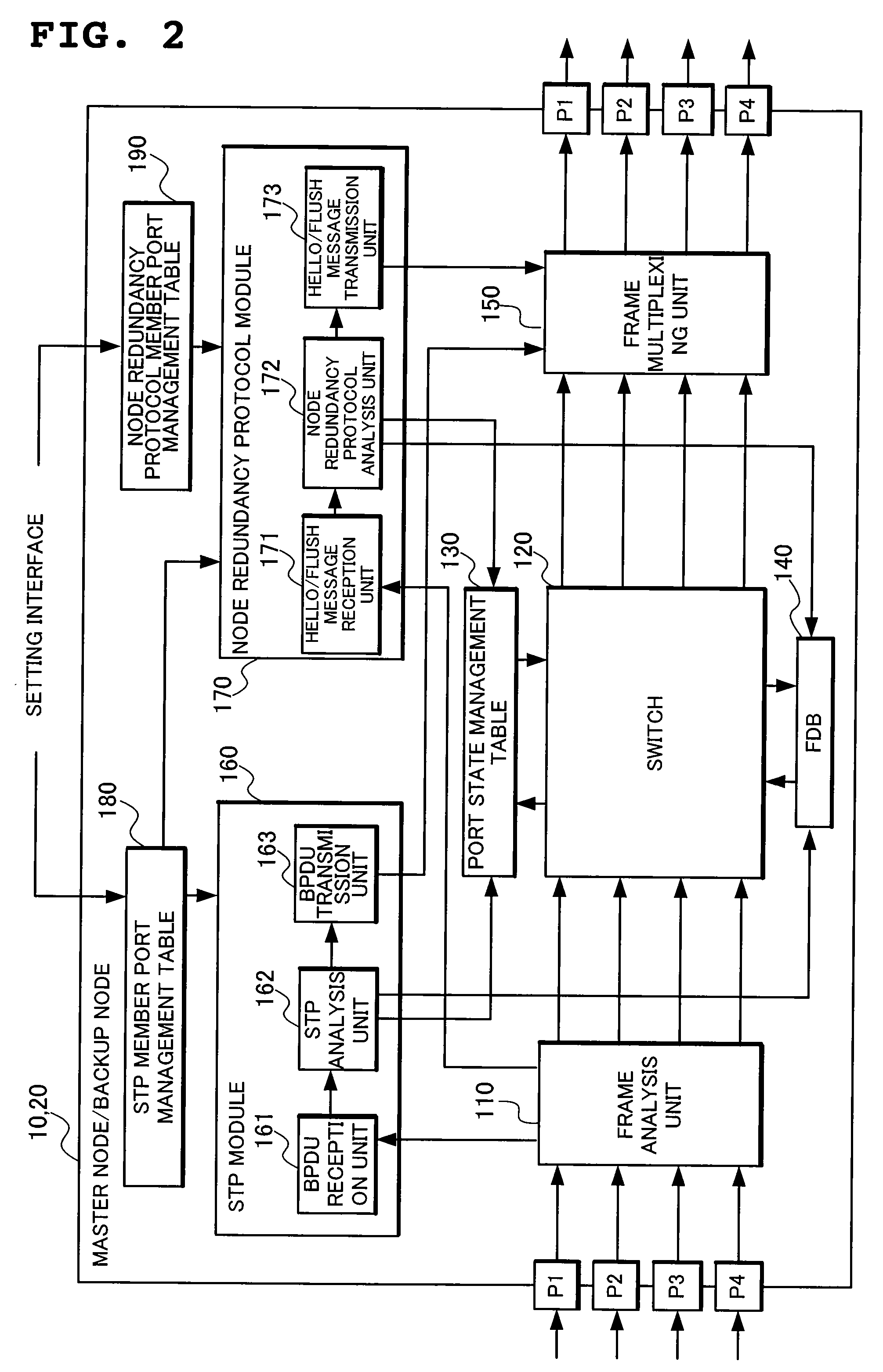
[0047] The present invention enables, by bringing a state of a port under the management of other protocol out of the management of the node redundancy protocol, contention between port management states by the node redundancy protocol and other protocol to be avoided, as well as enabling, by transmitting a Flush message to all the nodes connected to a member port under the management of the node redundancy protocol at the time when operation states of the master node and the backup node under the node redundancy protocol switch, flushing of an FDB of a node connected to a member port under the management of other protocol to be executed.

Problems solved by technology

When the node 1 develops a fault in the above-described STP network, a problem occurs that the node 5 is allowed to execute no frame transfer at all to the terminals under the node 3 and the node 2.
Possible failure different from the above-described down of the master node is cut-off of a link.
There occurs a problem, however, that frame transfer is disabled when a conventional node redundancy protocol is applied to a node in a network to which other protocol which manages a port state of a port (hereinafter referred to as other protocol) such as the STP, for example, is applied.

Method used


Image

  • Network system, node, node control program, and network control method
  • Network system, node, node control program, and network control method
  • Network system, node, node control program, and network control method

Examples


first embodiment

[0100] Detailed description will be made of a method of making a node forming an STP network be redundant in the first embodiment.

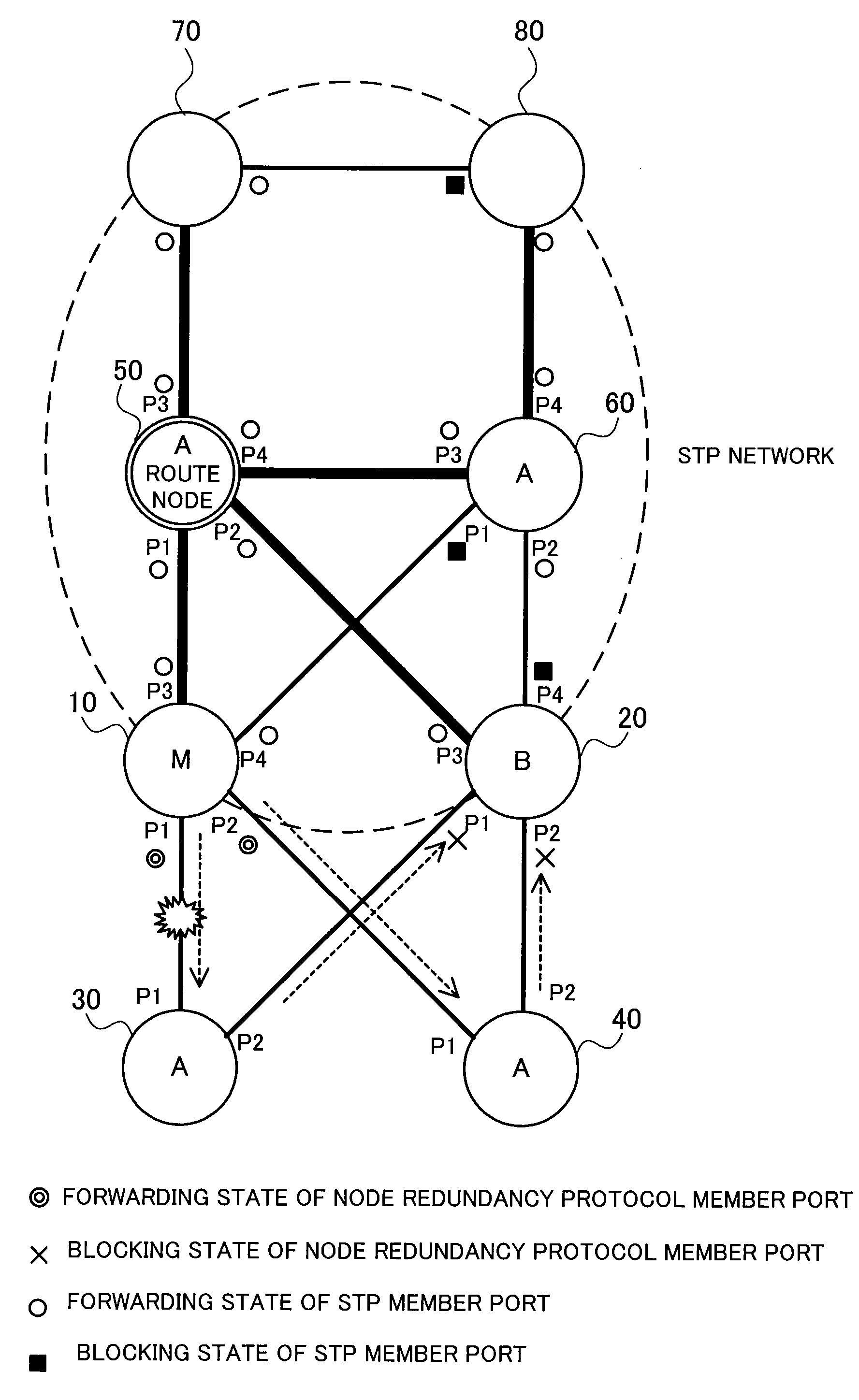
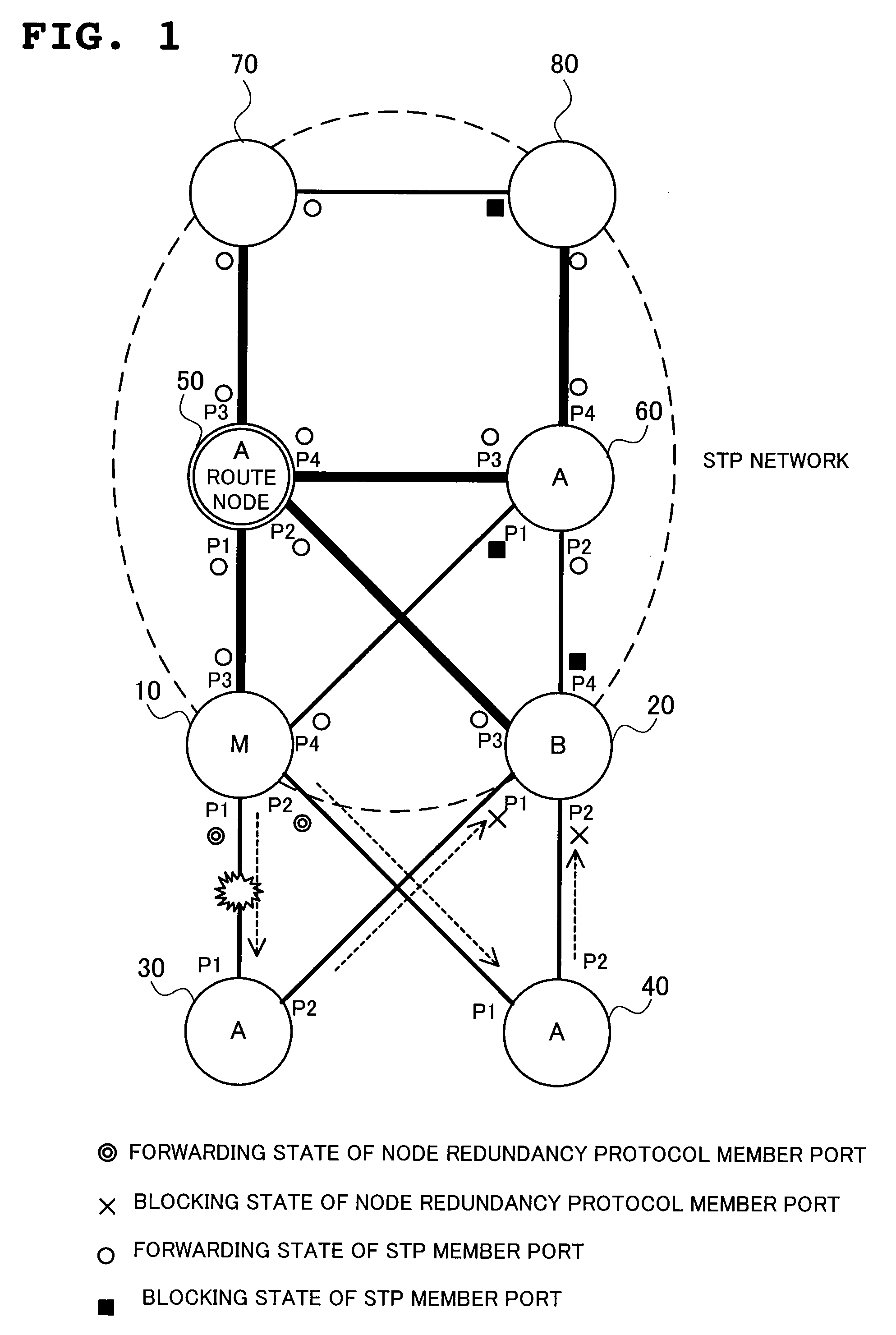
[0101]FIG. 1 is a diagram showing a structure of a network system to which the present invention is applied.

[0102] To ports P3 and P4 of a master node 10 and a backup node 20, nodes 50 and 60 belonging to an STP network are connected respectively and to ports P1 and P2 of the master node 10 and the backup node 20, nodes 30 and 40 not belonging to the STP network are connected respectively.

[0103] In addition, to the nodes 50 and 60 belonging to the STP network, nodes 70 and 80 are connected respectively, which nodes 70 and 80 form the STP network together with the master node 10, the backup node 20 and the nodes 50 and 60.

[0104] To the master node 10 and the backup node 20, a node redundancy protocol of the present invention is applied, with one of the master node 10 and the backup node 20 being in an operation state of a master mode and the other bein...

second embodiment

[0230] Next, a network system according to a second embodiment of the present invention will be described.

[0231] In the second embodiment, description will be made of a method of applying the node redundancy protocol of the present invention to a network system in which a plurality of VLAN (Virtual LAN) are set.

[0232]FIG. 20 is an example of application of the node redundancy protocol of the present invention to a network system in which three VLAN 401, 402 and 403 are set, which shows a state of the network system for each VLAN.

[0233] In the VLAN 401, the node 50 is a route node of the STP network and the operation states of the master node 10 and the backup node 20 are in the master mode and the backup mode, respectively.

[0234] In the VLAN 402, the master node 10 is a route node of the STP network and the operation states of the master node 10 and the backup node 20 are in the backup mode and the master mode, respectively.

[0235] In the VLAN 403, the node 70 is a route node of...

third embodiment

[0255] Next, a network system according to a third embodiment of the present invention will be described.

[0256] As to a node redundancy protocol according to the third embodiment, description will be made of a method which enables a node in an STP network be redundant without making improvement of a node adapted to an existing STP even a structure in which the nodes 50 and 60 of FIG. 1 include only the STP module 360 similarly to a node provided in an ordinary STP network.

[0257] Since when a node adapted to an existing STP is used as the nodes 50 and 60 in FIG. 1 and the node redundancy protocol according to the first embodiment is applied to the network system of FIG. 1, the node adapted to an existing STP is not allowed to recognize a control frame (Hello message or a Flush message) of the node redundancy protocol, there occurs a problem that the node is not allowed to function as an Aware node of the node redundancy protocol. 5 More specifically, there is a problem that a Hello...


PUM


Abstract

A network system in which a network adopting a node redundancy protocol and a network adopting an STP protocol as other protocol for managing a state of a port coexist, which is configured to manage, by the STP protocol as other protocol, a state of a port which belongs to a master node 10 and a backup node 20 forming the network adopting the STP protocol and is under the management of the node redundancy protocol and also under the management of the STP protocol, and in which the master node 10 or the backup node 20 transmits a Hello message as a control frame for monitoring a node and a link to all or a part of nodes connected to the port under the management of the node redundancy protocol, as well as transmitting a Flush message as a control frame for rewriting a forwarding database to all or a part of nodes connected to the port under the management of the node redundancy protocol at the time of switching to a master mode.

Description

FIELD OF THE INVENTION [0001] The present invention relates to a network system enabling service operation to be continued without stopping communication when such a failure occurs as node-down or link cut-off in a network and, more particularly, to a network system enabling communication to be continued when a failure occurs due to node redundancy. DESCRIPTION OF THE RELATED ART [0002] Description will be first made, with respect to one example, of a procedure of transferring a frame in a network where a frame is transferred by using information related to a frame transfer path calculated by a Spanning Tree Protocol (STP) (hereinafter referred to as an STP network) as one of protocols for managing a state of a port. [0003] Assume, for example, that in a network having such network topology as shown in FIG. 45, a heavy path (spanning tree) in FIG. 45 is calculated by the STP. [0004] At the transfer of a frame from a terminal under a node 5 to a terminal under a node 3 in this networ...

Claims


Application Information

Patent Timeline
Patent Type & Authority Applications(United States)
IPC IPC(8): H04J3/14H04J1/16H04L45/02H04L45/586
CPCH04L12/4641H04L45/04H04L49/552H04L45/28H04L45/48H04L45/22H04L45/484
Inventor OGASAWARA, DAISAKUENOMOTO, NOBUYUKIMIZOGUCHI, HAJIMESUNADA, KEIICHIUMAYABASHI, MASAKIHIDAKA, YOUICHIIWATA, ATSUSHI
Owner NEC CORP
Learn More