Surfboard fin system

Inactive Publication Date: 2007-11-08
SCHMIDT KENNETH E
View PDF12 Cites 13 Cited by
  • Summary
  • Abstract
  • Description
  • Claims
  • Application Information

AI Technical Summary

Benefits of technology

[0003] Briefly, the present invention relates to a fin which includes a generally horizontal hydrofoil intersecting or connecting with a typical vertical fin. The generally horizontal hydrofoil of the invention is designed using principles of hydrodynamics, that is, the forces generated by the flow of water over a hydrofoil or wing, to create a force that pulls downward on the fin

Problems solved by technology

Current fin designs may result in undesirable horiz

Method used


Image

  • Surfboard fin system
  • Surfboard fin system
  • Surfboard fin system

Examples


Embodiment Construction

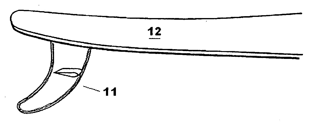
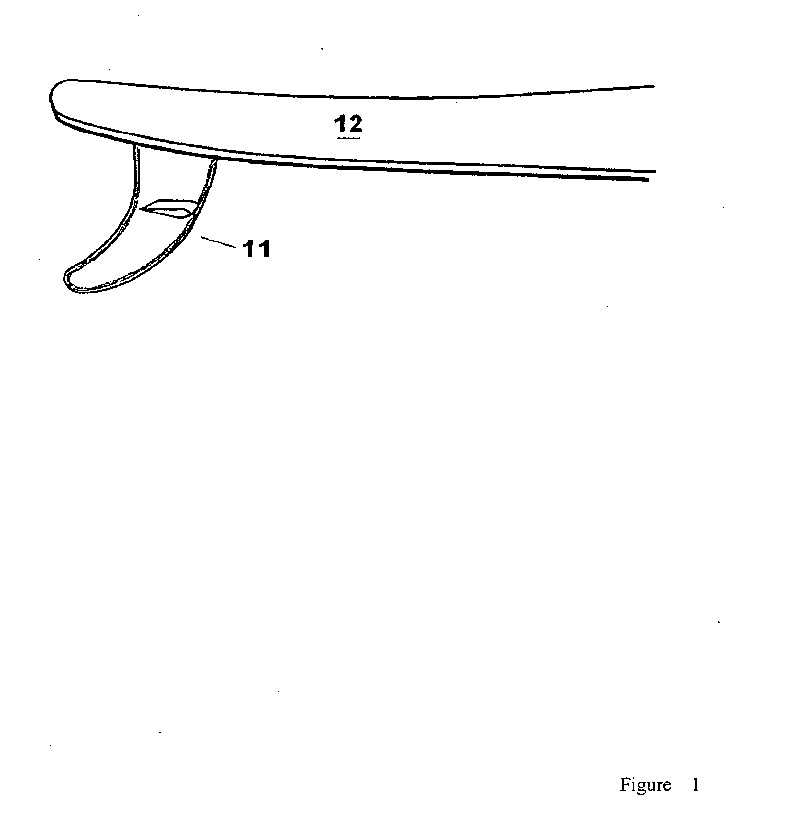
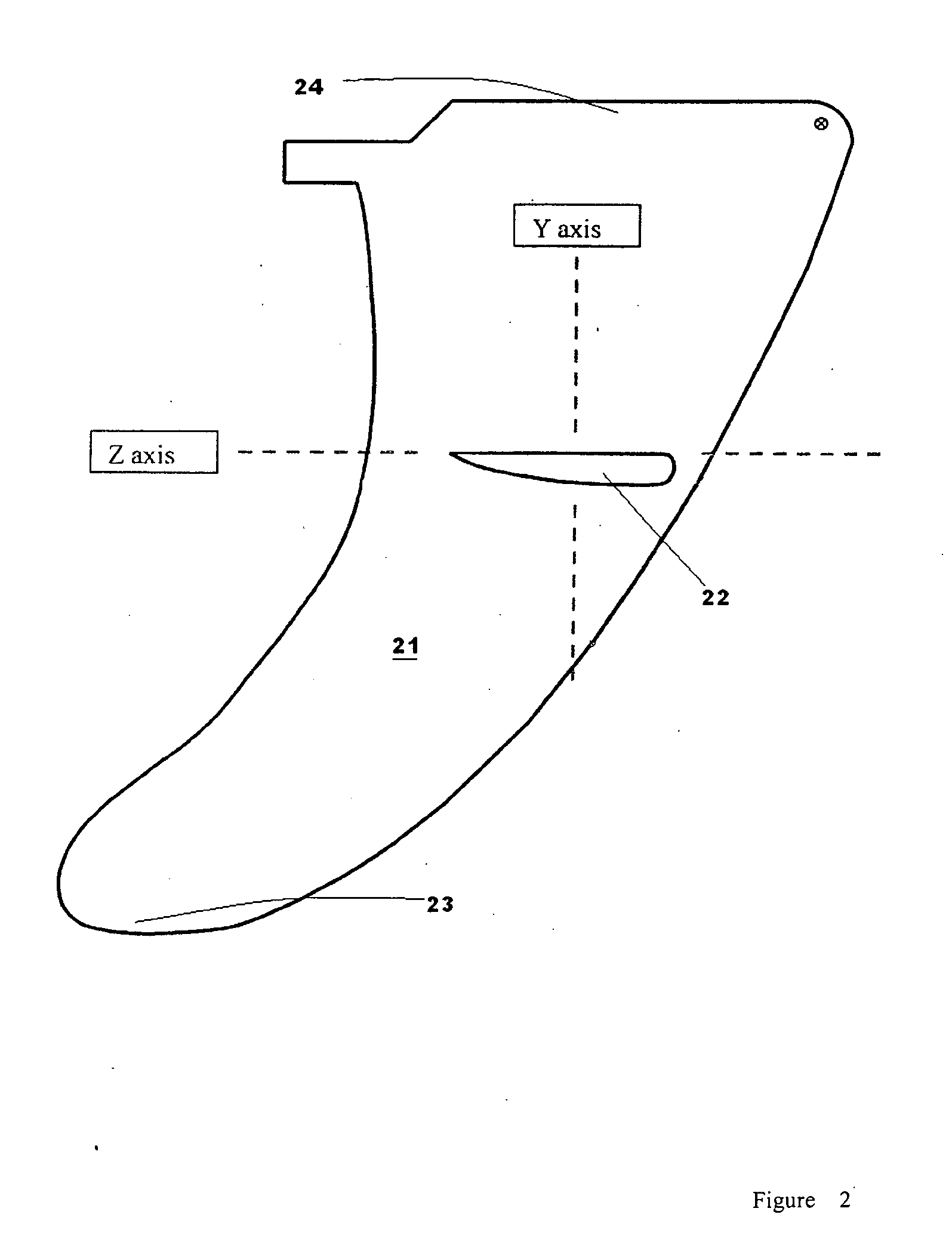
[0026] A surfboard with a fin system of the invention typically includes at least one vertical fin 21, to provide lateral stability and directional control, and a horizontal section or foil 22 attached to the vertical fin 21 to provided vertical stability and negative lift. Vertical stability and negative lift are generated by the inverted wing shape of the horizontal fin or hydrofoil. The term “horizontal” is intended to broadly describe a hydrofoil 22 attached to the vertical fin, and does not require that the foil be limited to any particular angle as compared to the vertical fin 21 or the plane of the surfboard. Moreover, the generally horizontal fin or fin construction which provides which provides negative lift, need not be attached to a vertical fin. For example, the negative lift fin constructs described may be positioned on the underside of a surfboard by means of a rod or post independent from a vertical fin.

[0027] The vertical fin 21 may be of any shape, and generally ha...


PUM


Abstract

The present invention relates to a surfboard fin system which includes a generally horizontal hydrofoil intersecting or connecting with one or more vertical fins. The generally horizontal hydrofoil of the invention is designed using principles of hydrodynamics, that is, the forces generated by the flow of water over a hydrofoil or wing, to create a force that pulls downward on the fin system and, in turn, downward on the tail end of the water planing hull or surfboard.

Description

FIELD OF THE INVENTION [0001] This invention is related to water planing hulls, such as surfboards, and the design of hydrodynamic fins to stabilize the performance of the planing hull as it moves through the water. BACKGROUND OF THE INVENTION [0002] Surfboards may generally be described as water planing hulls and are constructed of various lengths, width, shapes and thicknesses. Surfboards have a forward tip which is connected by generally symmetrically shaped sides to the rearward tail. Surfboards currently available in the marketplace typically have a large vertical fin located underneath and near the tail of the surfboard. The large fin is usually located on the center line of the surfboard. Some surfboards have additional smaller fins, which are offset at equal distances from the center line. Current fin designs may result in undesirable horizontal or lateral stability of the entire surfboard. Moreover, fin designs typically do not affect the vertical or pitch stability of the ...

Claims


Application Information

Patent Timeline
IPC IPC(8): B63B1/00
CPCB63B35/7923B63B35/7926B63B32/64B63B32/40
Inventor SCHMIDT, KENNETH E.
Owner SCHMIDT KENNETH E
Why Eureka
Try Eureka