
Mobile terminal having acoustic transducer and control method thereof

a technology of acoustic transducer and mobile terminal, which is applied in the direction of charging/accumulating, loudspeakers, stereophonic arrangments, etc., and can solve problems such as user inconvenien

Inactive Publication Date: 2007-11-15
LG ELECTRONICS INC
View PDF11 Cites 71 Cited by
  • Summary
  • Abstract
  • Description
  • Claims
  • Application Information

AI Technical Summary

Benefits of technology

[0012]It is contemplated that the connection terminals include a charging connection terminal for charging the battery of each of the acoustic transducers by using one of the power of the battery mounted in the terminal body and an extra power source connected with the mobile terminal. It is further contemplated that the mobile terminal further includes a locking part is formed between each acoustic tr

Problems solved by technology

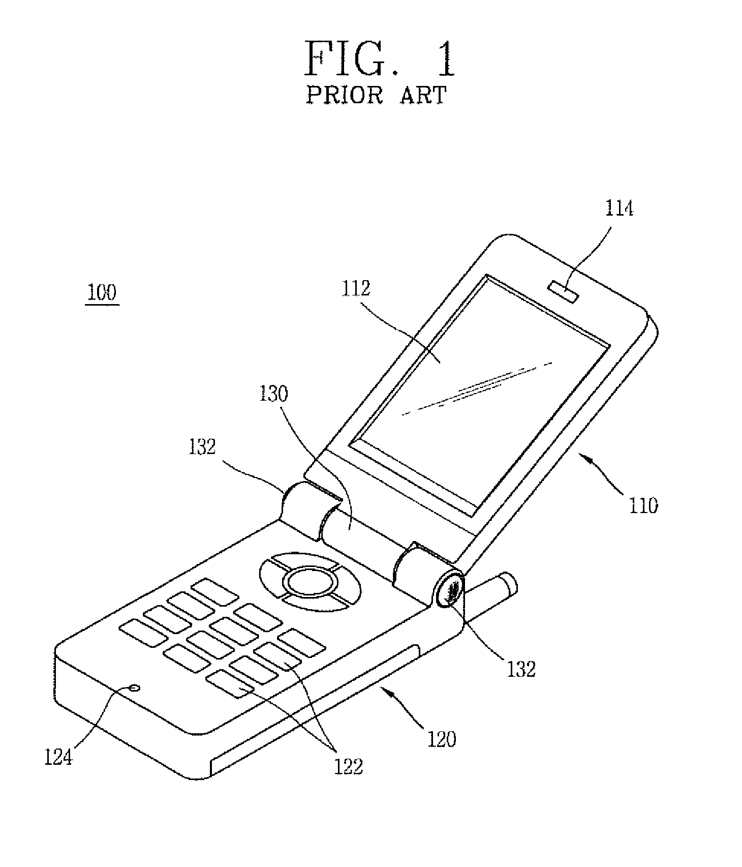
However, the related art mobile terminal 100 has a problem because the pair of speakers are fixed at the terminal body, the user must use a separate earphone or headset to make and receive a call while driving, for example.
In addition, when the user changes the mobile terminal 100 to the call mode while he / she is enjoying music, the user must hold the terminal to perform call communication by using the receiver and microphone mounted on the terminal, causing user inconvenience.

Method used


Image

  • Mobile terminal having acoustic transducer and control method thereof
  • Mobile terminal having acoustic transducer and control method thereof
  • Mobile terminal having acoustic transducer and control method thereof

Examples


first embodiment

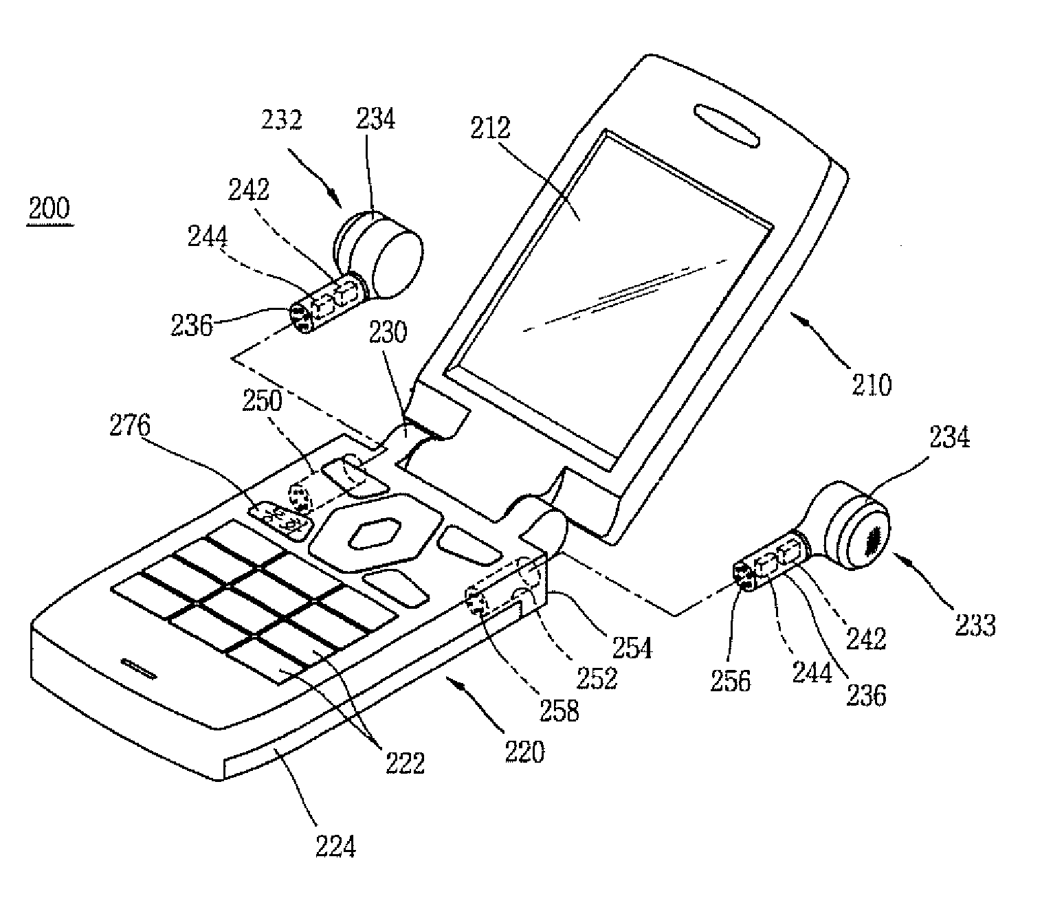
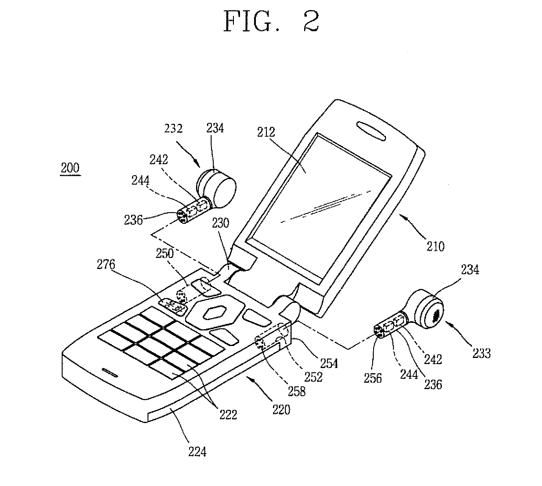
[0033]FIG. 2 is a perspective view of a mobile terminal 200 according to the present invention.

[0034]The mobile terminal 200, according to the first embodiment of the present invention, includes a display unit 210 having a display 212 for displaying information, a terminal body 220 rotatably connected with the display unit 210 and including a keypad 222 mounted on its front surface and inputting information and a battery 224 mounted on its rear surface, and acoustic transducers 232 and 233 detachably mounted at the terminal body 220.

[0035]A hinge part 230 is formed between the display unit 210 and the terminal body 220 to support the display unit 210 to be relatively rotatable with respect to the terminal body 220.

[0036]As illustrated in FIG. 2, the mobile terminal 200 is a folder type mobile terminal in which the display unit 210 and the terminal body 220 are rotatably connected by the hinge part 230. However, the present invention can be applicable to any type of mobile terminal s...

second embodiment

[0063]FIG. 7 is a perspective view of a mobile terminal 300 according to the present invention.

[0064]A mobile terminal 300 according to the second embodiment of the present invention includes a terminal body 320 having a display 312 and a keypad 322 and a pair of acoustic transducers 332 and 333 detachably mounted in a lengthwise direction at both edge portions of the terminal body 320.

[0065]The acoustic transducers 332 and 333 have the same structure as that of the acoustic transducers 232 and 233 of the first embodiment of the present invention, so its description will be omitted.

[0066]A pair of receiving parts 386 and 388 are formed at both edge portions of the terminal body 320, in which the pair of acoustic transducers 332 and 333 are detachably mounted.

[0067]When the acoustic transducers 332 and 333 are mounted in the terminal body 320, they are operated as speakers to emanate sound, and when the mobile terminal 300 is in a call mode, one of the acoustic transducers 332 and 33...


PUM


Abstract

A mobile terminal having acoustic transducers and method for using the same are provided. The acoustic transducers are detachably mounted in a terminal body. When the acoustic transducers are mounted in the terminal body, they are operated as speakers, and when the acoustic transducers are separated from the terminal body, the acoustic transducers are operated as at least one of a wireless earphone and the microphone.

Description

CROSS REFERENCE TO RELATED APPLICATION[0001]Pursuant to 35 U.S.C. § 119(a), this application claims the benefit of earlier filing date and right of priority to Korean Application No. 10-2006-0042128, filed May 10, 2006, the contents of which are hereby incorporated by reference herein in their entirety.FIELD OF THE INVENTION[0002]The present invention relates to a mobile terminal and, more particularly, to a mobile terminal that can be used as a speaker when mounted in a terminal body and can be used as a wireless earphone when separated from the terminal body.DISCUSSION OF THE RELATED ART[0003]FIG. 1 is a perspective view of the related art mobile terminal 100. The related art mobile terminal 100 includes a display unit 110 including a display 112 for displaying information, a terminal body 120 connected with the display unit 110 such that it can be opened and closed and having a keypad 122 mounted on its front surface for inputting information, a hinge part 130 rotatably connectin...

Claims


Application Information

Patent Timeline
IPC IPC(8): H04R5/02
CPCH04M1/0218H04M1/0256H04M1/0258H04M1/03H04M1/6066H04R2420/07H04R1/1025H04R5/033H04R2201/107H04R2400/01H04R1/1016H04B1/38
Inventor KIM, MYOUNG-JAE
Owner LG ELECTRONICS INC
Learn More