Method for displaying face detection frame, method for displaying character information, and image-taking device

Active Publication Date: 2007-11-15
FUJIFILM CORP
View PDF2 Cites 64 Cited by
  • Summary
  • Abstract
  • Description
  • Claims
  • Application Information

AI Technical Summary

Benefits of technology

[0038]According to the present invention, since the display position of the face detection frame is adapted to be corrected in accordance with the movement of the image-taking device from the time of obtaining the image used for the face detection in the live preview even if the update cycle of the live preview is fast, the position of the face on the live preview can be fixed relative to the position of the face detection frame even when the image-taking device is panned/tilted. Similarly, since character information representing the ch

Problems solved by technology

If a face detection frame is displayed on a live preview which is being continuously picked up and displayed, however, since it takes a few seconds for one face detection, there is a problem that the position of the face on the live preview and the face detection frame become misaligned wh

Method used


Image

  • Method for displaying face detection frame, method for displaying character information, and image-taking device
  • Method for displaying face detection frame, method for displaying character information, and image-taking device
  • Method for displaying face detection frame, method for displaying character information, and image-taking device

Examples


Example

First Embodiment

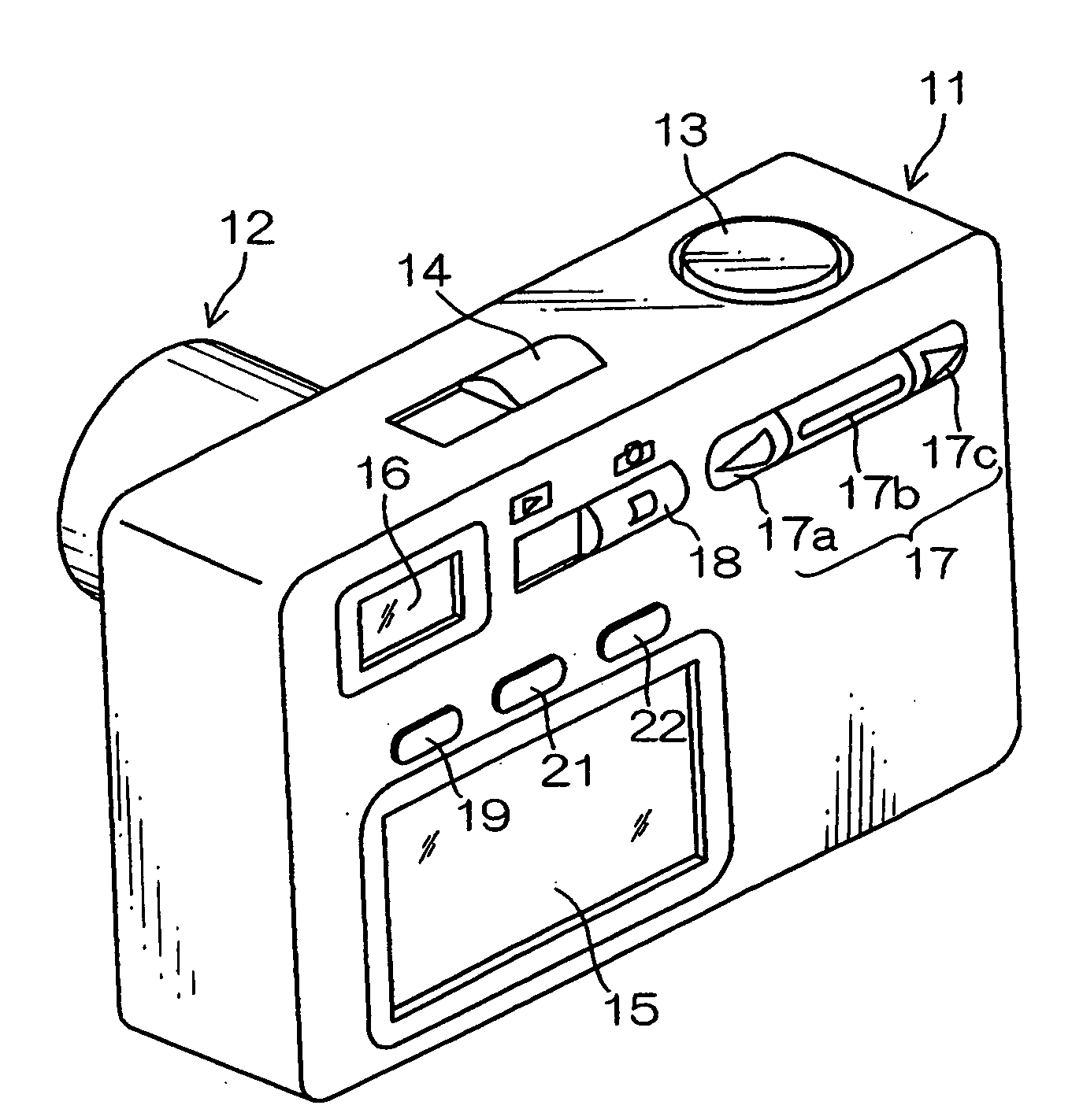
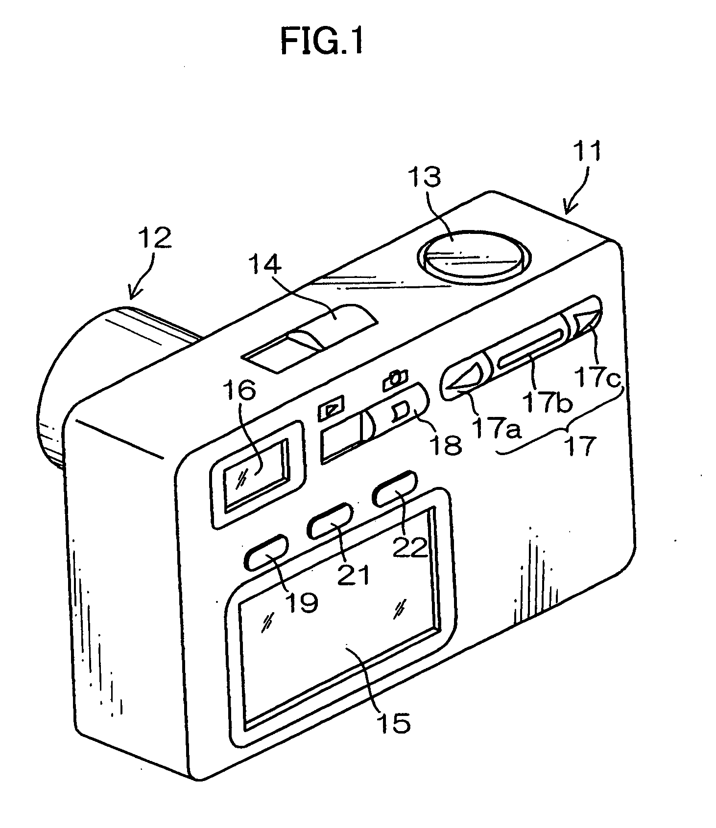
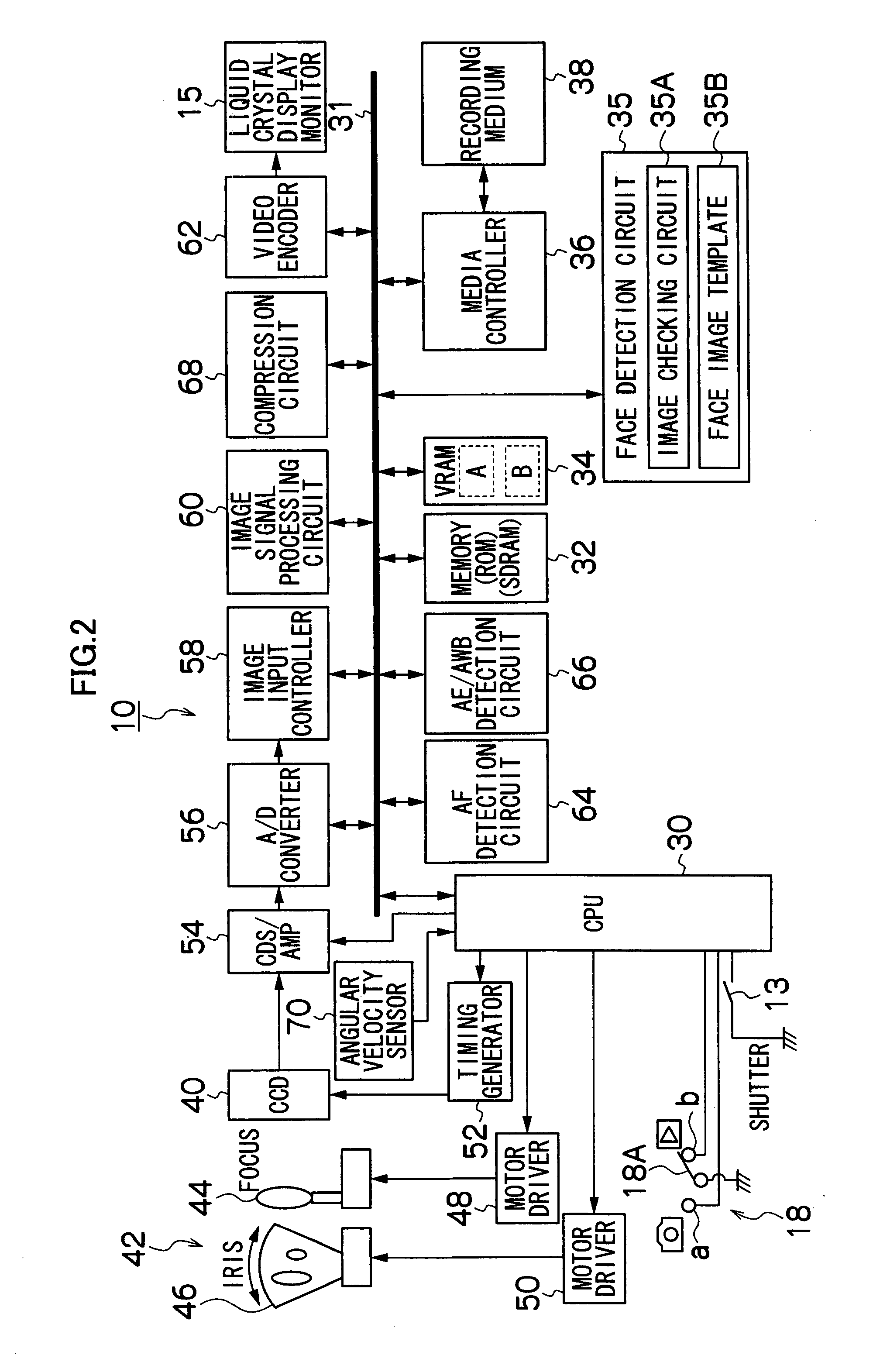
[0065]FIG. 2 is a block diagram illustrating an exemplary internal structure of a first embodiment of the digital camera 10 shown in FIG. 1.

[0066]The overall operation of the digital camera 10 is governed by a central processing unit (CPU) 30. The CPU 30 acts as a control device which controls this camera system according to a predetermined program, and also acts as a computing device which performs various types of operations such as automatic exposure (AE) operations, automatic focus (AF) operations, or white balance (WB) adjustment operations.

[0067]A memory 32, being connected with the CPU 30 via a bus 31, includes a ROM which stores programs executed by the CPU 30 and various types of data needed for controls, and an SDRAM which is used as a deployment area for the programs and a working area for computation by the CPU 30 as well as a temporary storage area for image data. A VRAM 34 is a temporary memory exclusively used for image data and includes areas A and B ...

Example

Second Embodiment

[0115]FIG. 6 is a block diagram illustrating an exemplary internal structure of a second embodiment of the image-taking device (digital camera 10-2) according to the present invention. Note that the same reference numerals are used to refer to the elements in common with the digital camera 10 in FIG. 2 and the detailed description thereof will be omitted.

[0116]The digital camera 10-2 of the second embodiment shown in FIG. 6 is different from the digital camera 10 of the first embodiment shown in FIG. 2 in that it has a camera shake compensation function.

[0117]More specifically, the digital camera 10-2 has a motor driver 72 used to cause (part of) the taking lens 40 to vibrate to the right and left or up and down. The CPU 30 detects a camera shake of the digital camera 10-2 based on an angular velocity signal of the angular velocity sensor 70, and controls the motor driver 72 to cancel the camera shake and optically prevent the camera shake from occurring.

[0118]Also,...

Example

Third Embodiment

[0126]FIG. 8 is a block diagram illustrating an exemplary internal structure of a third embodiment of the image-taking device (digital camera 10-3) according to the present invention. Note that the same reference numerals are used to refer to the elements in common with the digital camera 10 in FIG. 2 and the detailed description thereof will be omitted.

[0127]The digital camera 10-3 of the third embodiment shown in FIG. 8 is different from the first embodiment mainly in that it has a motion vector detection circuit 80 which detects a motion vector of a subject instead of the angular velocity sensor 70 in the first embodiment.

[0128]The motion vector detection circuit 80 detects an amount of movement and a direction of movement (motion vector) on the screen between one image and the next image based on the live preview obtained continuously through the CCD 40, etc. This information indicating the motion vector is added to the CPU 30.

[0129]The CPU 30 determines the disp...


PUM


Abstract

An aspect of the present invention provides a method for displaying a face detection frame in an image-taking device, which obtains an image signal representing a subject continuously at a predetermined cycle, displays a live video preview on a display device based on the obtained image signal and detects a face of the subject included in the live preview based on the obtained image signal, and superimposes a face detection frame surrounding the detected face of the subject on the live preview for display on the display device, wherein the movement of the image-taking device from the time of obtaining the image used for the face detection is detected, and wherein the display position of the face detection frame is corrected according to the detected movement of the image-taking device on the basis of the display position of the face detection frame relative to the image used for the face detection.

Description

BACKGROUND OF THE INVENTION[0001]1. Field of the Invention[0002]The present invention relates to a method for displaying a face detection frame, a method for displaying character information, and an image-taking device, and more particularly to technology for fitting the position of the face detection frame or the like onto a live preview.[0003]2. Description of the Related Art[0004]Digital cameras which can detect a face from a subject have become commercially practical. These cameras can capture an image of a subject with proper focus and exposure by detecting a face and performing automatic focus control (AF) and automatic exposure control (AE) in the face area, even if the AF and AE based on the normal imaging are difficult. In addition, such a digital camera can display a face detection frame in the detection area when it detects a face so that an operator can determine whether or not the digital camera has detected a face.[0005]Japanese Patent Application Laid-Open No. 2005-28...

Claims


Application Information

Patent Timeline
IPC IPC(8): G06F17/00G06V30/10G06V30/142
CPCG06K9/228G06K9/723H04N5/23248H04N5/23212H04N5/23219H04N5/225G06V30/142G06V30/268G06V30/10H04N23/00H04N23/673H04N23/61H04N23/611H04N23/68H04N23/632H04N23/635H04N25/134
Inventor AYAKI, KENICHIROMIZUTA, TOMOYUKI
Owner FUJIFILM CORP
Why Eureka
Try Eureka