This helps you quickly interpret patents by identifying the three key elements:
Problems solved by technology
Method used
Benefits of technology
Benefits of technology
[0024] It is another aspect of the present invention to provide a tandem color image forming device having an image forming cartridge in which a plurality of image forming units are modularized in a body, and in which when it is assembled in a mounting frame formed in a main body, center shafts of photosensitive bodies disposed in the image forming units can be accurately fixed in position, thereby obtaining quality images consistently.
[0025] It is another aspect of the present invention to provide a tandem color image forming device having an image forming cartridge in which a plurality of image forming units are modularized in a body, and which by having at least a portion of center shafts of photosensitive bodies disposed in the image forming units, to be movable when it is assembled in a mounting frame formed in a main body, and to easily assemble and disassemble the center shafts of the photosensitive bodies in and from a corresponding shaft receiving part of the mounting frame, even though they are fabricated so as not to just join with the shaft receiving part, and thereby can be easily fabricated and assembled.
[0031] The image forming cartridge preferably further comprises an elastic member elastically pressing the image forming units corresponding to the rest of the center shafts of the photosensitive bodies in at least one direction to assist moving of the image forming units corresponding to the rest of the center shafts of the photosensitive bodies in the at least one of the direction.
Problems solved by technology
Fabricating the dimensions in both side components to accurately coincide with one another as described above can complicate the design of the fabricating mold, and can induce assembling errors when assembling both of the side components.
This is difficult to achieve, and causes assembling efficiency to decrease and increases assembling time, thereby lowering manufacturing productivity.
Method used
Image
Click on the blue label to locate the original text in one second.
Reading with bidirectional positioning of images and text.
Examples
embodiment 1
[0060]FIGS. 6 and 7 illustrate a tandem color image forming device 100 according to a first preferred embodiment of the present invention.
[0061] The tandem color image forming device 100 according to a first embodiment of the present invention comprises a paper feeding unit 121 to feed sheet of printing paper stacked in a paper cassette 120; an image forming cartridge 150 having first, second, third and fourth image forming units 110Y, 110M, 110C and 110K for forming toner images of four colors (typically yellow, magenta, cyan, and black) disposed vertically in parallel to be modularized in a body, and an intermediate transfer unit 107 having a belt-shaped intermediate transfer element 170 such as a photosensitive belt rotatably supported on plural rollers 171, 172, 173 and 174 (FIG. 11) at a left side of first, second, third and fourth drum-shaped photosensitive bodies 101Y, 101M, 101C, and 101K disposed respectively in the first, the second, the third and the fourth image forming...
embodiment 2
[0098]FIG. 14 illustrates a mounting frame 108′ and an image forming cartridge 150′ of a tandem color image forming device according to a second embodiment of the present invention.
[0099] Unlike the color image forming device 100 of the first embodiment described with reference to FIGS. 6 through 13, the tandem color image forming device of the second embodiment is constructed to transfer toner images formed on photosensitive bodies 110Y′, 101M′, 101C′, and 101K′ directly onto a sheet of printing paper through a transfer unit 105A′ such as a transfer drum, without using an intermediate transfer unit that receives the toner images formed on the photosensitive bodies 101Y′, 101M′, 101C′, and 101K′ and then retransfers them onto the sheet of printing paper.
[0100] The tandem color image forming device of the second embodiment comprises a paper feeding unit (not shown) to feed sheets of printing paper contained in a paper cassette (not shown), an image forming cartridge 150′ having fir...
embodiment 3
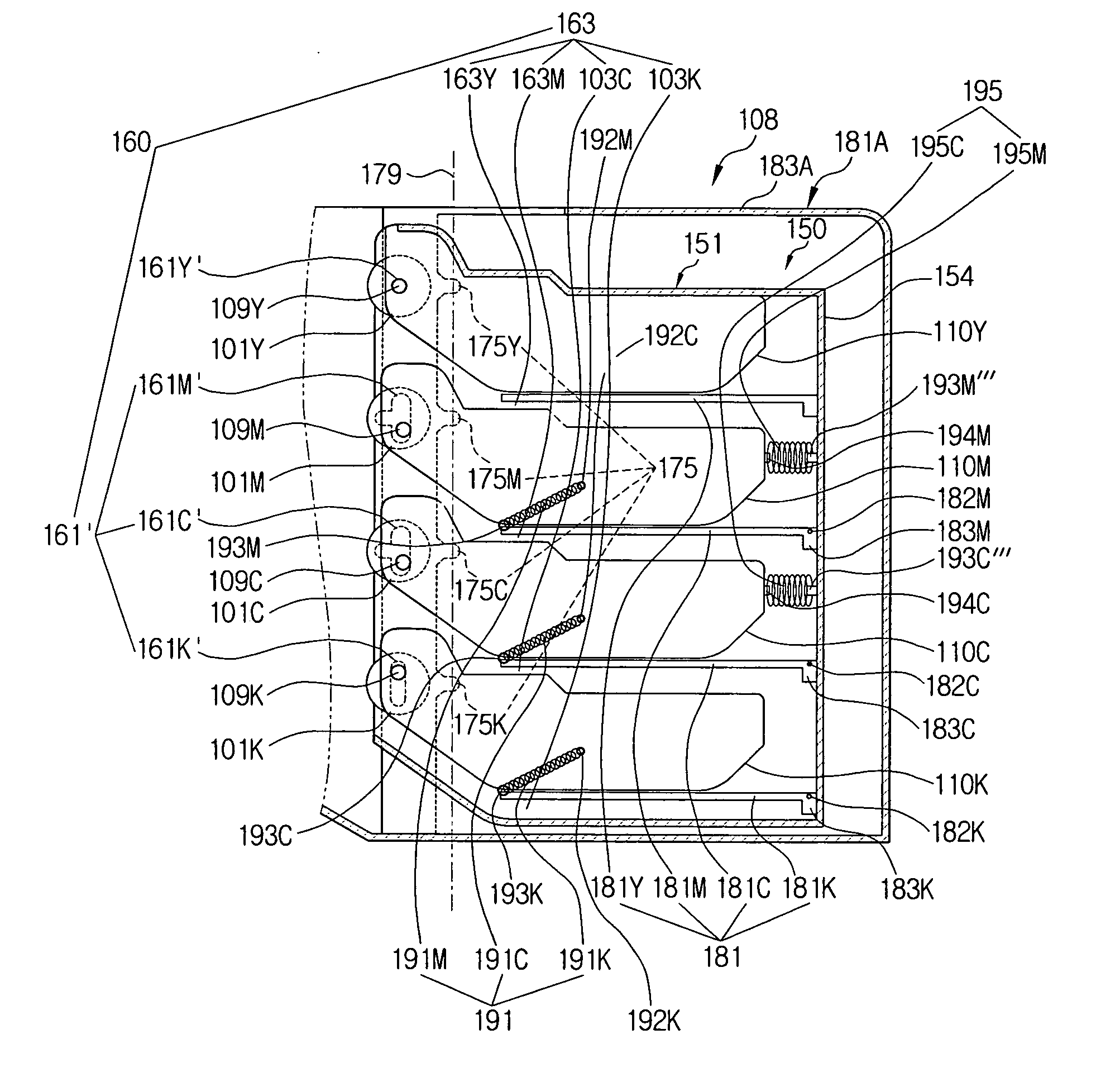
[0118]FIG. 15 illustrates an image forming cartridge 150″ and a mounting frame 108″ of a tandem color image forming device according to a third embodiment of the present invention.
[0119] The tandem color image forming device of the third embodiment comprises a paper feeding unit (not shown), an image forming cartridge 150″, an intermediate transfer unit (not shown), a mounting frame 108″, a transfer unit (not shown), and a fusing unit (not shown).
[0120] The description regarding the paper feeding unit, the intermediate transfer unit, the mounting frame 108″, the transfer unit, and the fusing unit except for the image forming cartridge 150″ will be omitted here, as it is identical to that of the ones of the tandem color image forming device 100 of the first embodiment that are described above with reference to FIGS. 6 through 13.
[0121] The image forming cartridge 150″ includes a cartridge frame 151″ having first, second, third and fourth image forming units 110Y″, 110M″, 110C″ and...
PUM
Abstract
A tandem color image forming device comprises an image forming cartridge including a cartridge frame having a supporting part receiving a plurality of image forming units in parallel to modularize in a body, and a movable fixing part supporting at least one of a plurality of center shafts of photosensitive bodies disposed in the plurality of image forming units to be unmovable, but rotatable, and the other of the plurality of center shafts of the photosensitive bodies to be movable and rotatable when the plurality of image forming units are received in the cartridge frame, and a mounting frame formed at a main body to mount the image forming cartridge therein, and having a shaft receiving part formed at a position corresponding to both ends of the center shafts of the photosensitive bodies of the image forming units to receive both ends of the center shafts of the photosensitive bodies when the image forming cartridge is mounted in the mounting frame. The tandem color image forming device can accurately fix the center shafts of the photosensitive bodies of the image forming units in position when the image forming cartridge is assembled in the mounting frame, thereby obtaining a high quality image reliably.
Description
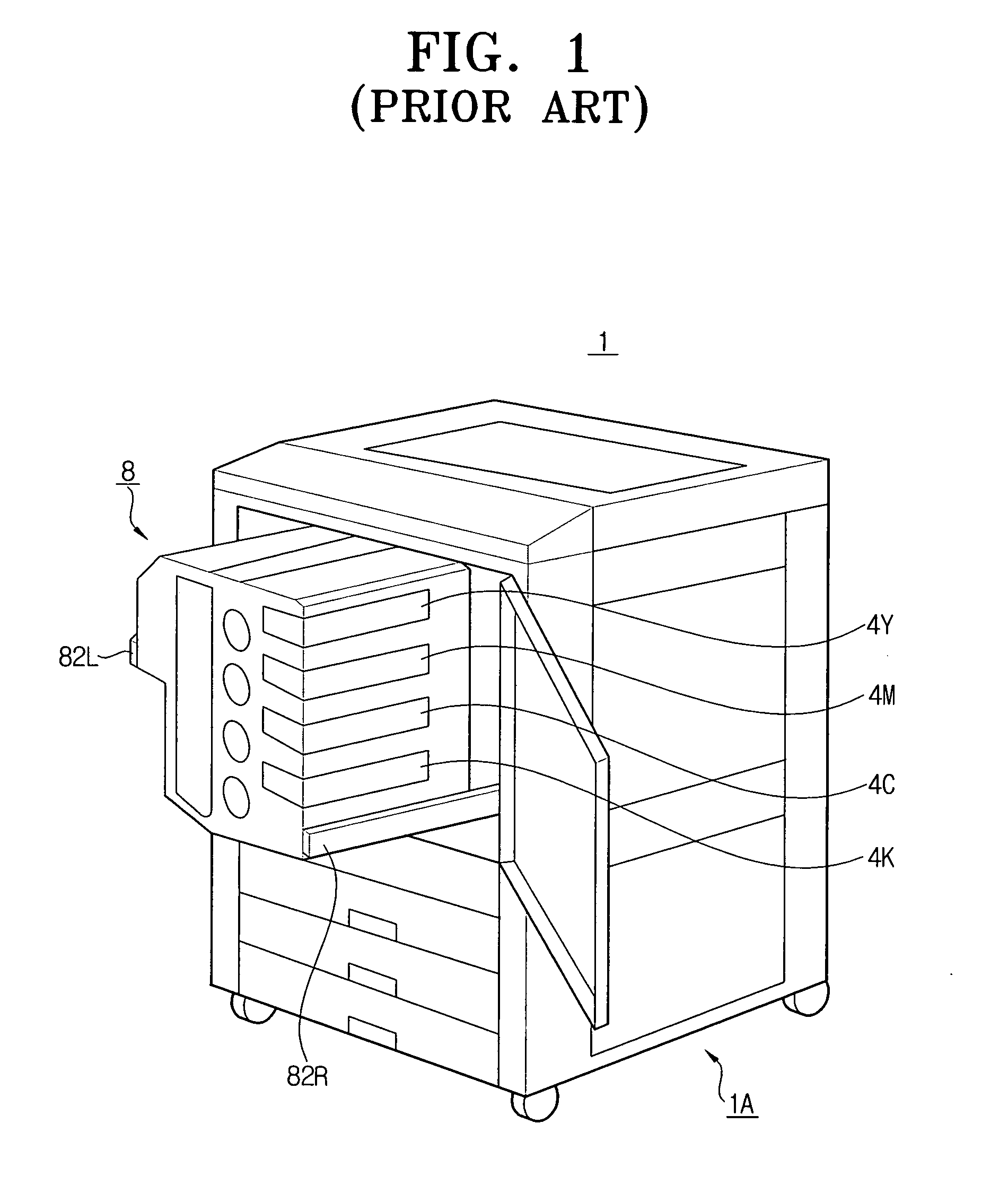
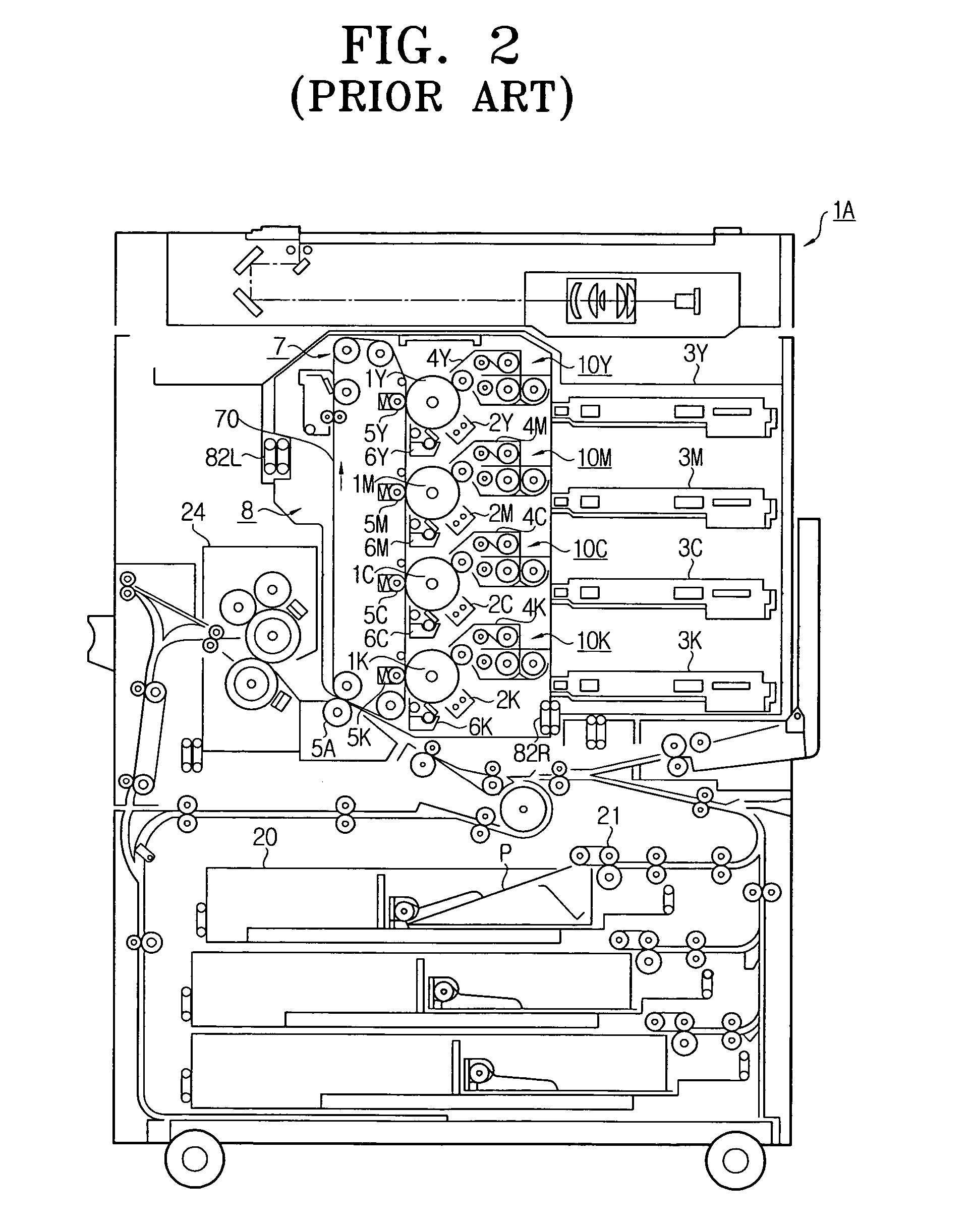
CROSS-REFERENCE TO RELATED APPLICATIONS [0001] This application claims priority from Korean Patent Application No. 2003-45044, filed on Jul. 3, 2003, in the Korean Intellectual Property Office, the entire contents of which are incorporated herein by reference. BACKGROUND OF THE INVENTION [0002] 1. Field of the Invention [0003] The present invention relates to an electrophotographic image forming device such as a printer, copier, and facsimilemachine. More particularly, the present invention relates to a tandem color image forming apparatus to transfer toner images formed respectively on a plurality of photosensitive bodies by a plurality of corresponding image forming units, onto an intermediate transfer unit or printing medium. [0004] 2. Description of the Related Art [0005] A conventional electrophotographic tandem color image forming device is provided with a plurality of image forming units disposed in parallel, a plurality of photosensitive bodies, each being disposed in the c...
Claims
Application Information
Patent Timeline
Application Date:The date an application was filed.
Publication Date:The date a patent or application was officially published.
First Publication Date:The earliest publication date of a patent with the same application number.
Issue Date:Publication date of the patent grant document.
PCT Entry Date:The Entry date of PCT National Phase.
Estimated Expiry Date:The statutory expiry date of a patent right according to the Patent Law, and it is the longest term of protection that the patent right can achieve without the termination of the patent right due to other reasons(Term extension factor has been taken into account ).
Invalid Date:Actual expiry date is based on effective date or publication date of legal transaction data of invalid patent.

