Distortion-based method and apparatus for buffer control in a communication system

a communication system and buffer control technology, applied in the field of distortion-based buffer control techniques in digital communication systems, can solve the problems of variable transmission delay, limited end-to-end delay desired by the cost of the decoder, and variable perceptual audio coder, so as to achieve constant distortion level, consistent perceptual quality, and variation of perceived distortion over time

Active Publication Date: 2006-06-13
AVAGO TECH INT SALES PTE LTD
View PDF11 Cites 15 Cited by
  • Summary
  • Abstract
  • Description
  • Claims
  • Application Information

AI Technical Summary

Benefits of technology

[0010]Generally, a method and apparatus are disclosed for controlling a buffer in a communication system, such as a digital audio broadcasting (DAB) communication system. The present invention recognizes that a more consistent perceptual quality over time provides for a more pleasing auditory experience to a listener. The present invention further recognizes that a more consistent perceptual quality is achieved over time using a relatively constant distortion level. Thus,

Problems solved by technology

As a result of this scheme, the transmission delay is also variable.
Therefore, one disadvantage of having to use different noise thresholds for different target bit rates is the necessity of manually tuning the psychoacoustic model of the perceptual audio coder 110 for each specific target bit rate, in order to achieve a reasonable level of efficiency and performance.
However, since different types of audio signals result in significantly different bit demands,

Method used


Image

  • Distortion-based method and apparatus for buffer control in a communication system
  • Distortion-based method and apparatus for buffer control in a communication system
  • Distortion-based method and apparatus for buffer control in a communication system

Examples


Embodiment Construction

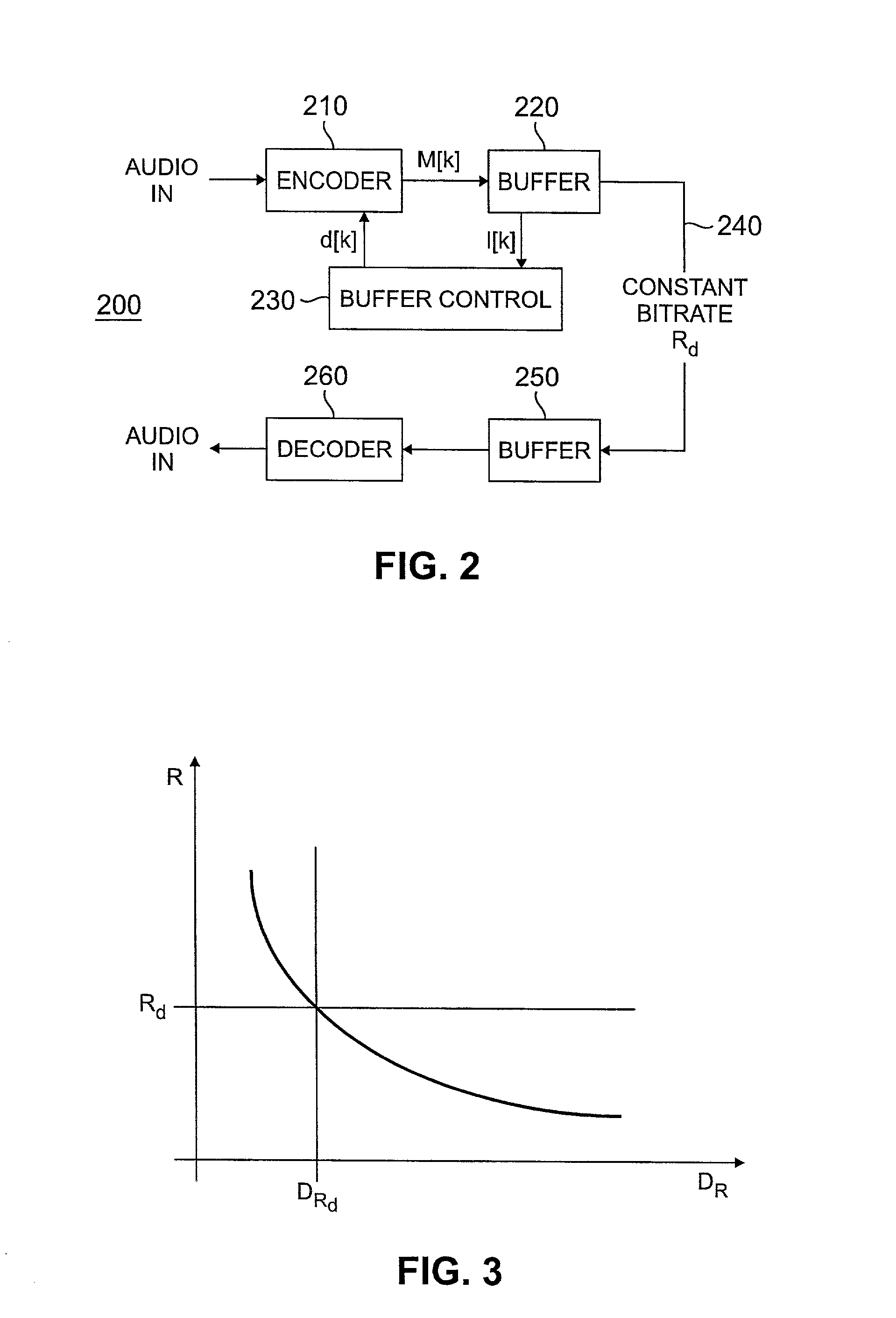
[0019]FIG. 2 illustrates a communication system 200 in accordance with the present invention. As shown in FIG. 2, the communication system 200 has an audio encoder 210 and decoder 260 with a buffered bit stream for a constant bit rate transmission of the bits. The buffered bit stream is achieved using an encoder buffer 220 and a decoder buffer 250. As shown in FIG. 2, the M[k] bits of the encoded frame, at the time of each frame k, are put into the FIFO buffer 220 while Rd bits are removed from the FIFO buffer 220 by the constant bit rate transmission channel 240. The number of data bits in the encoder buffer 220 can be expressed iteratively as:

l[k]=l[k−1]+M[k]−Rd,  (1)

with an initial buffer level of l[0] equal to ld bits. A buffer control element 230 monitors the buffer level l[k] and influences the encoding process to ensure that the buffer 220 does not overflow. Buffer underflow can be easily prevented by padding additional (non-used) bits to the frame when underflow would occur....


PUM


Abstract

A method and apparatus are disclosed for controlling a buffer in a communication system, such as a digital audio broadcasting (DAB) communication system. A more consistent perceptual quality over time provides for a more pleasing auditory experience to a listener. Thus, the disclosed bit allocation process determines, for each frame, a distortion d[k] at which the frame is to be encoded. Generally, the distortion d[k] is determined to minimize (i) the probability for a buffer overflow, and (ii) the variation of perceived distortion over time. A buffer level is controlled by partitioning a signal into a sequence of successive frames; estimating a distortion rate for a number of frames; and selecting a distortion such that the variance of the buffer level is bounded by a specified value. In one implementation, a signal is coded by partitioning the signal into a sequence of successive frames; encoding each frame k for each of a plurality of distortions Di to compute a frame bitrate; estimating an average bitrate Ri[k] for each of said plurality of distortions Di given current and past frame bitrates; interpolating between each of said pair of values for said average bitrate Ri[k] and said plurality of distortions Di to obtain an approximation of a function that maps a distortion to an estimated average bitrate; and encoding each frame with a distortion level determined from said function.

Description

FIELD OF THE INVENTION[0001]The present invention relates generally to digital audio broadcasting (DAB) and other types of digital communication systems, and more particularly, to buffer control techniques for such digital communication systems.BACKGROUND OF THE INVENTION[0002]Proposed systems for providing digital audio broadcasting are expected to provide near compact disk (CD)-quality audio, data services and more robust coverage than existing analog FM transmissions. Digital audio broadcasting systems compress an audio signal using a digital audio encoder, such as a perceptual audio coder (PAC). Perceptual audio coders reduce the amount of information needed to represent an audio signal by exploiting human perception and minimizing the perceived distortion for a given bit rate. Perceptual audio coders are described, for example, in D. Sinha et al., “The Perceptual Audio Coder,” Digital Audio, Section 42, 42-1 to 42-18. (CRC Press, 1998), incorporated by reference herein. General...

Claims


Application Information

Patent Timeline
IPC IPC(8): G10L19/00H04B1/66
CPCH04B1/665H04B1/66
Inventor FALLER, CHRISTOF
Owner AVAGO TECH INT SALES PTE LTD
Why Eureka
Try Eureka