Polishing-pad laminated structure, polishing-pad positioning instrument, and method of attaching a polishing pad to a polishing table

Pending Publication Date: 2020-01-23
EBARA CORP
View PDF8 Cites 0 Cited by
  • Summary
  • Abstract
  • Description
  • Claims
  • Application Information

AI Technical Summary

Benefits of technology

[0023]According to the embodiments described above, the position of the polishing pad with respect to the polishing table is adjusted in a state where the first release sheet having a small surface area has been removed. Since the polishing-pad laminated structure can be moved relatively freely on the polishing table, the through-hole of the polishing pad can be precisely aligned with the sensor head disposed in the polishing table. Further, immediately after the alignment of the through-hole of the polishing pad with the sensor head is completed, the exposed portion of the ad

Problems solved by technology

However, it is difficult to accurately align the through-hole of the polishing pad with the sensor head disposed in the polishing table.
In particular, since the through-hole of the polis

Method used


Image

  • Polishing-pad laminated structure, polishing-pad positioning instrument, and method of attaching a polishing pad to a polishing table
  • Polishing-pad laminated structure, polishing-pad positioning instrument, and method of attaching a polishing pad to a polishing table
  • Polishing-pad laminated structure, polishing-pad positioning instrument, and method of attaching a polishing pad to a polishing table

Examples


Example

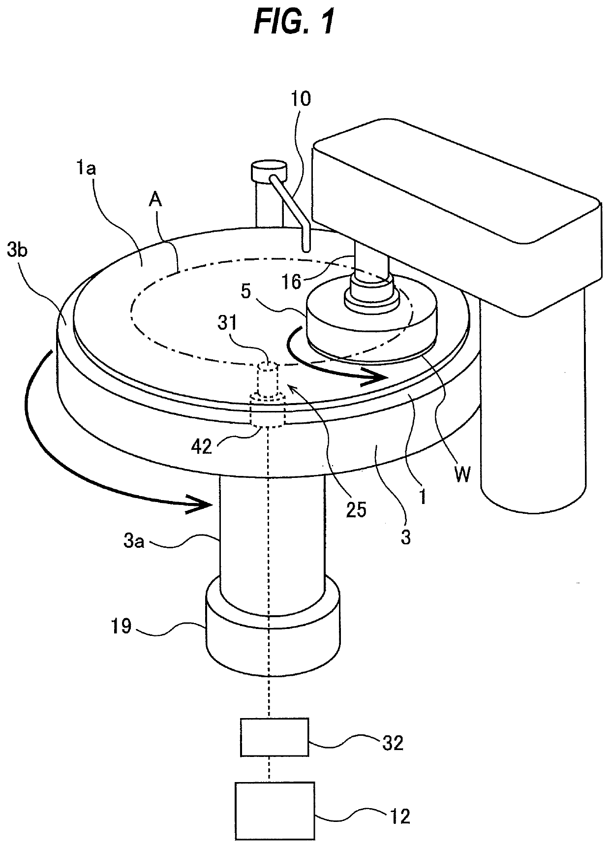
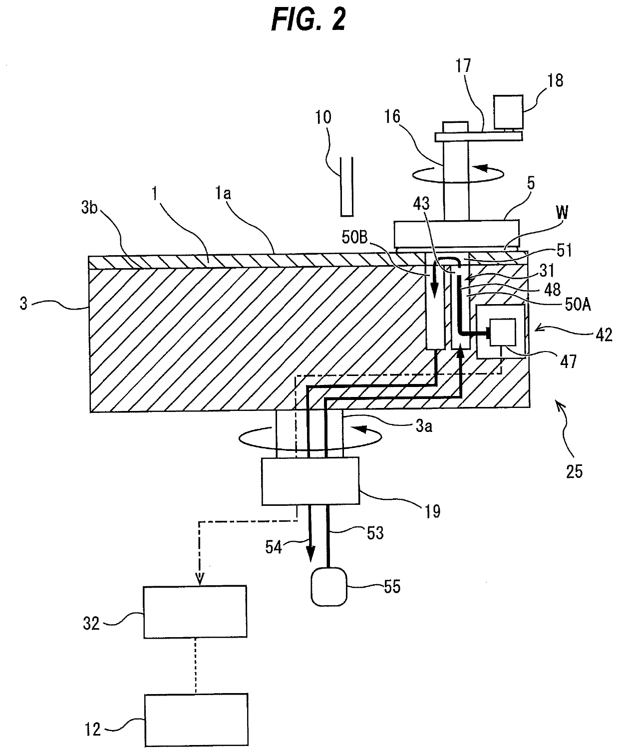
[0101]Embodiments will be described below with reference to the drawings. FIG. 1 is a view showing an embodiment of a polishing apparatus. As shown in FIG. 1, the polishing apparatus includes a polishing table 3 to which a polishing pad 1 having a polishing surface 1a is attached, a polishing head 5 for holding a wafer W, which is an example of a substrate, and pressing the wafer W against the polishing pad 1 on the polishing table 3 to polish the wafer W, a polishing-liquid supply nozzle 10 for supplying a polishing liquid (e.g., slurry) onto the polishing pad 1, and a polishing controller 12 for controlling polishing of the wafer W.

[0102]The polishing table 3 is coupled to a table motor 19 through a table shaft 3a, so that the polishing table 3 is rotated by the table motor 19 in a direction indicated by arrow. The table motor 19 is located below the polishing table 3. The polishing pad 1 is attached to a pad support surface 3b of the polishing table 3. The pad support surface 3b ...


PUM


Abstract

A polishing-pad laminated structure which allows for easy alignment of a through-hole of a polishing pad with a sensor head installed in a polishing table is disclosed. The polishing-pad laminated structure includes a polishing pad and a release sheet. The polishing pad has a through-hole located at a position corresponding to a position of a sensor head disposed in the polishing table. The release sheet covers an adhesive surface of the polishing pad. The release sheet is divided into at least a first release sheet and a second release sheet. The first release sheet has a surface area smaller than a surface area of the second release sheet.

Description

CROSS REFERENCE TO RELATED APPLICATION[0001]This document claims priority to U.S. Provisional Patent Application No. 62 / 691,119 filed Jun. 28, 2018, the entire contents of which are hereby incorporated by reference.BACKGROUND[0002]Manufacturing processes of semiconductor devices include a process of polishing a dielectric film, e.g., SiO2, and a process of polishing a metal film, e.g., copper or tungsten. Manufacturing processes of backside illumination CMOS sensor and through-silicon via (TSV) include a process of polishing a silicon layer (silicon wafer), in addition to the polishing processes of the dielectric film and the metal film.[0003]Wafer polishing is generally performed using a chemical mechanical polishing apparatus (or a CMP apparatus). This CMP apparatus is configured to polish a surface of the wafer by bringing the wafer into sliding contact with a polishing pad attached to a polishing table while supplying slurry onto the polishing pad. The polishing of the wafer is ...

Claims


Application Information

Patent Timeline
IPC IPC(8): B24B47/22B24B37/26B24B37/34B24B37/005
CPCB24B37/005B24B47/22B24B37/345B24B37/26
Inventor NOMURA, TOSHIKAZUKINOSHITA, MASAKITAKAHASHI, NOBUYUKISAKUGAWA, SUGURUKISHI, TAKASHI
Owner EBARA CORP
Why Eureka
Try Eureka