

Container Having a Rim or other Feature Encapsulated by or Formed From Injection-Molded Material
a technology of injection molding and rims, applied in the field of containers, to achieve the effects of facilitating washing, drying, and reuse of containers, strengthening and stabilizing the tray, and facilitating the washing and drying of the tray
- Summary
- Abstract
- Description
- Claims
- Application Information
AI Technical Summary
Benefits of technology
Problems solved by technology
Method used
Image

Examples
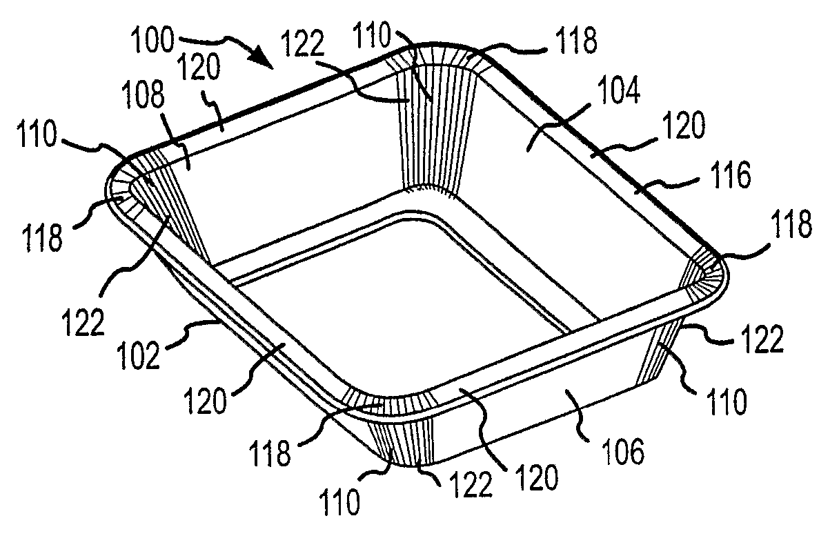
embodiment 100
[0214] The embodiment 100 may have only an encapsulated rim, or may have additional injection-molded features such as handles, hinges, coatings, ribs, and so forth. Encapsulated rims are further described next, and the additional features are described in more detail below.
[0215] The terms “plastic rim” and “encapsulated rim” are used interchangeably and may in fact refer to encapsulated rims made of a material other than plastic. Any injection-molded material capable of forming a rim encapsulating all or a portion of the tray flange 116 and providing a hermetic barrier is usable with the present invention. For example, an alternate embodiment of the invention may form a hermetic seal from rubbers, such as neoprene or butyl, rather than plastic.
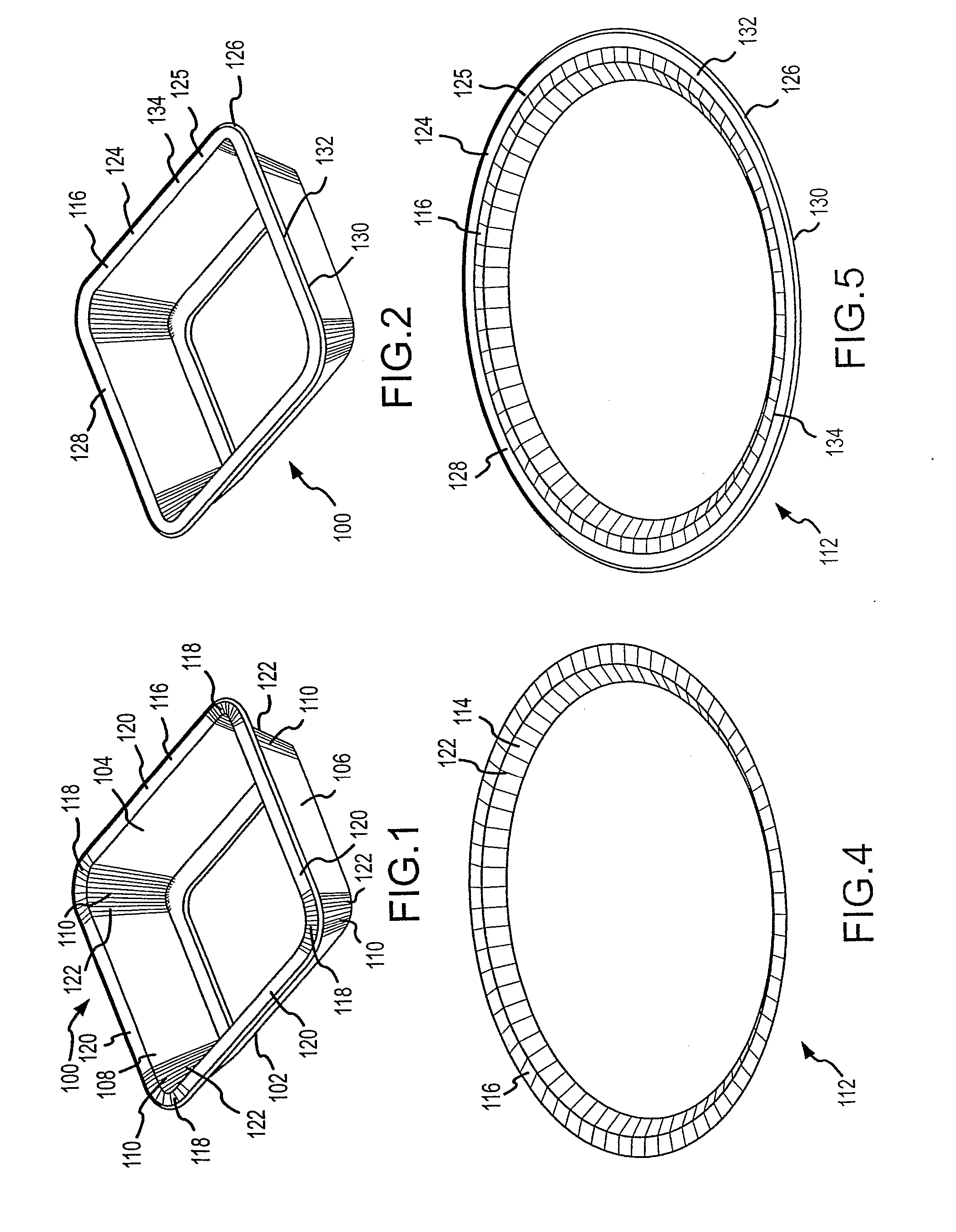
Fully-Encapsulated Rim
[0216] In one embodiment, as shown in FIGS. 2 and 5, the flange 116 is fully encapsulated to a substantially uniform thickness and width, to form an “encapsulated flange”124 with the possible exception of the outer ti...
first embodiment
[0389]FIG. 74 displays an open injection mold tool 536 and suitable for manufacturing a tray 100 and encapsulated rim 124 (see, e.g. FIG. 76) according to one embodiment of the present invention. Generally, an assembled tray 100 is inserted in the middle of the injection mold tool 536, as shown in FIG. 74. The flange 116 rests on a barrier wall 538 (FIG. 77), thus supporting the tray 100 and suspending it above the bottom of the injection mold tool. The barrier wall 538 comprises a portion of the bottom member 540 of the closed injection mold tool 536.
[0390] As part of the manufacturing process, any pleats 122 spaced along the tray 100 or flange 116 may be pressed prior to being placed in the injection mold tool 536 in order to at least partially flatten them. This simplifies the process of creating an hermetic seal across the pleat surface, as described below.
[0391] Once the tray 100 is properly positioned within the injection mold tool 536, the injection mold tool is closed, as ...
embodiment 1767
[0499]FIGS. 204-235 depict a folded, paperboard tray 1761 that has a flange 1763 extending outwardly from the sidewall 1765. The addition of this outwardly-folded flange enhances the ability to injection mold an encapsulated rim 1769 onto the tray. The injection mold tool clamps onto both sides of the outwardly-folded paperboard flange, which permits more efficient control of the flow of molten polymer. FIGS. 209-213 depict an alternate embodiment 1767 of the tray 1761 shown in FIGS. 204-208. FIGS. 214-216 depict trays 1761, similar to those shown in FIGS. 204-208, nested within one another. The encapsulated rim 1769 may enhance denesting operations.
[0500] In the embodiments depicted in FIGS. 202, 203, and 204-235, the folded tray may be composed of any type of paperboard (e.g., SBS, SUS, Kraft, CRB), printed or plain, that is adhesively laminated or extrusion coated with a polyolefin material or any other material such as paper, another paperboard, CPET, or the like.
Venting Featur...
PUM
 Abstract
Description
Claims
Application Information