Semiconductor light emitting device and method for manufacturing the same

a technology of semiconductors and light-emitting devices, which is applied in the direction of semiconductor devices, basic electric elements, electrical appliances, etc., can solve the problems of low light-emitting brightness, decreased light-emitting brightness, and low reliability of led devices, and achieve high reliability

Active Publication Date: 2007-11-22
STANLEY ELECTRIC CO LTD
View PDF17 Cites 33 Cited by
  • Summary
  • Abstract
  • Description
  • Claims
  • Application Information

AI Technical Summary

Benefits of technology

The patent is about a new technology that solves problems with traditional semiconductor light-emitting devices. The technology provides high reliability and methods of manufacture are also provided.

Problems solved by technology

The patent text discusses a problem with conventional LED devices that use a surplus storage part for the encapsulating resin, which can decrease light-emitting efficiency and cause peeling in the phase boundaries between the materials. The text proposes a solution to prevent these issues by providing a new LED device that does not require a surplus storage part and has improved cohesiveness between the optical lens and the encapsulating resin. The technical problem addressed by this patent is to provide a more stable and efficient LED device with improved light-emitting brightness and stability in its operation.

Method used


Image

  • Semiconductor light emitting device and method for manufacturing the same
  • Semiconductor light emitting device and method for manufacturing the same
  • Semiconductor light emitting device and method for manufacturing the same

Examples


Embodiment Construction

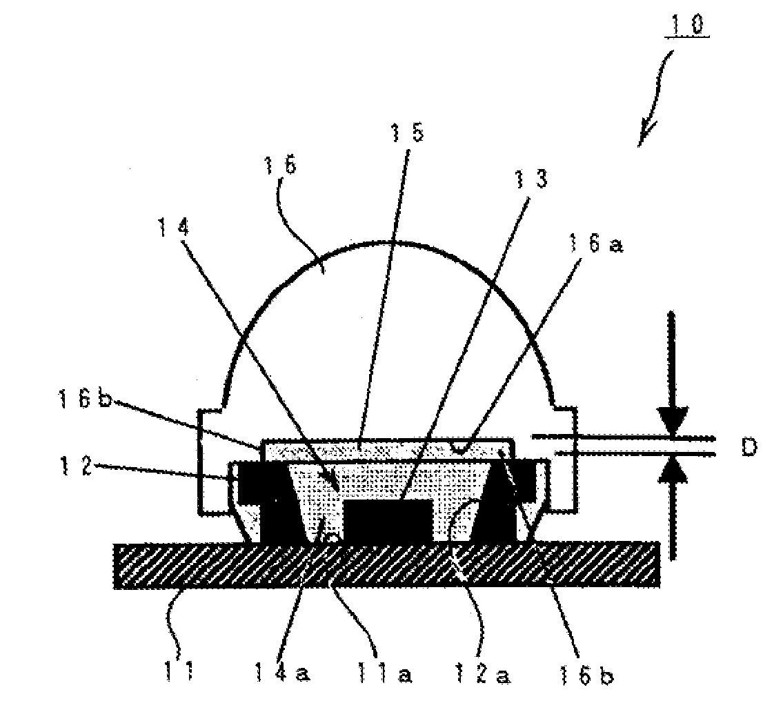
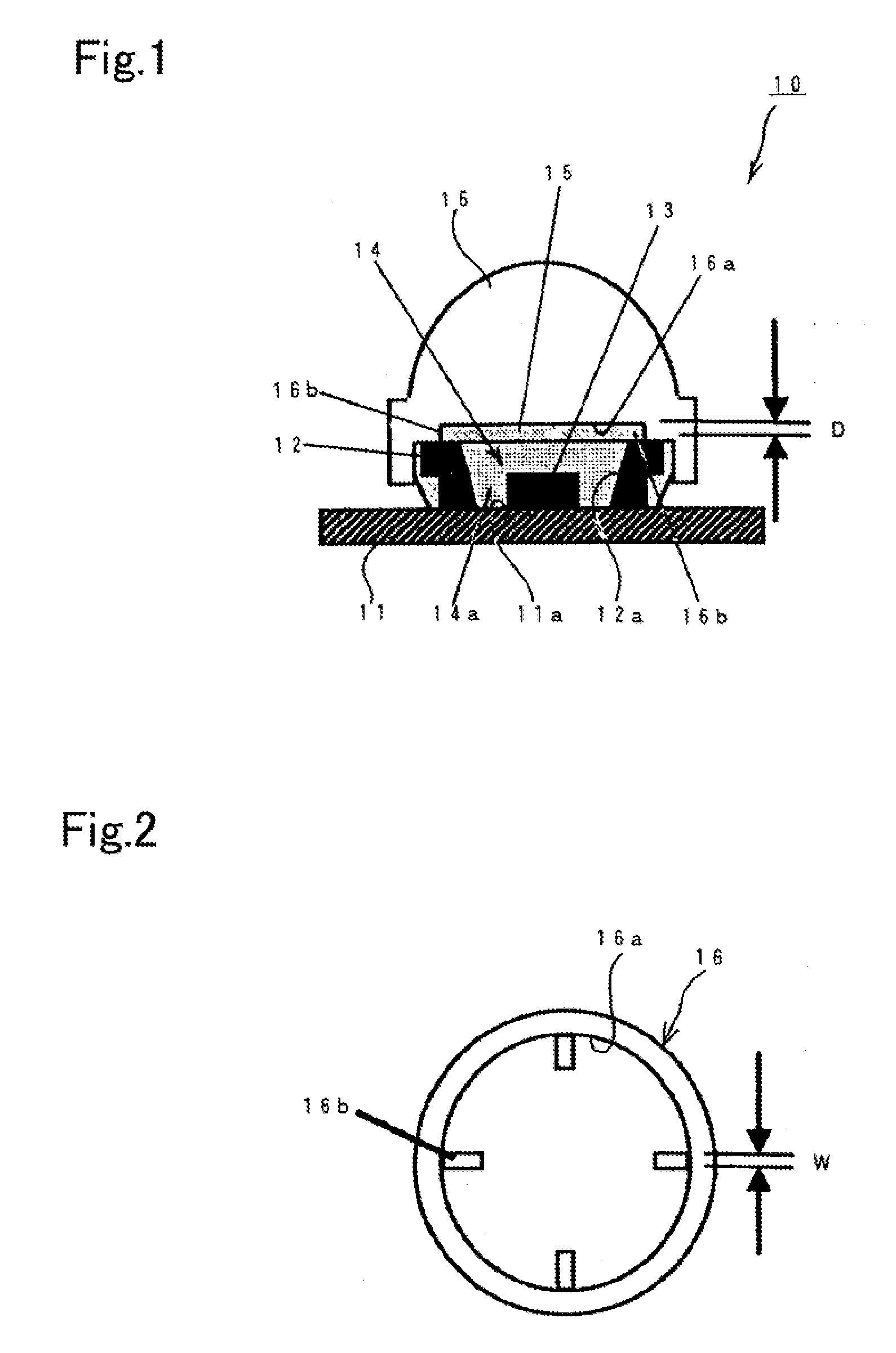
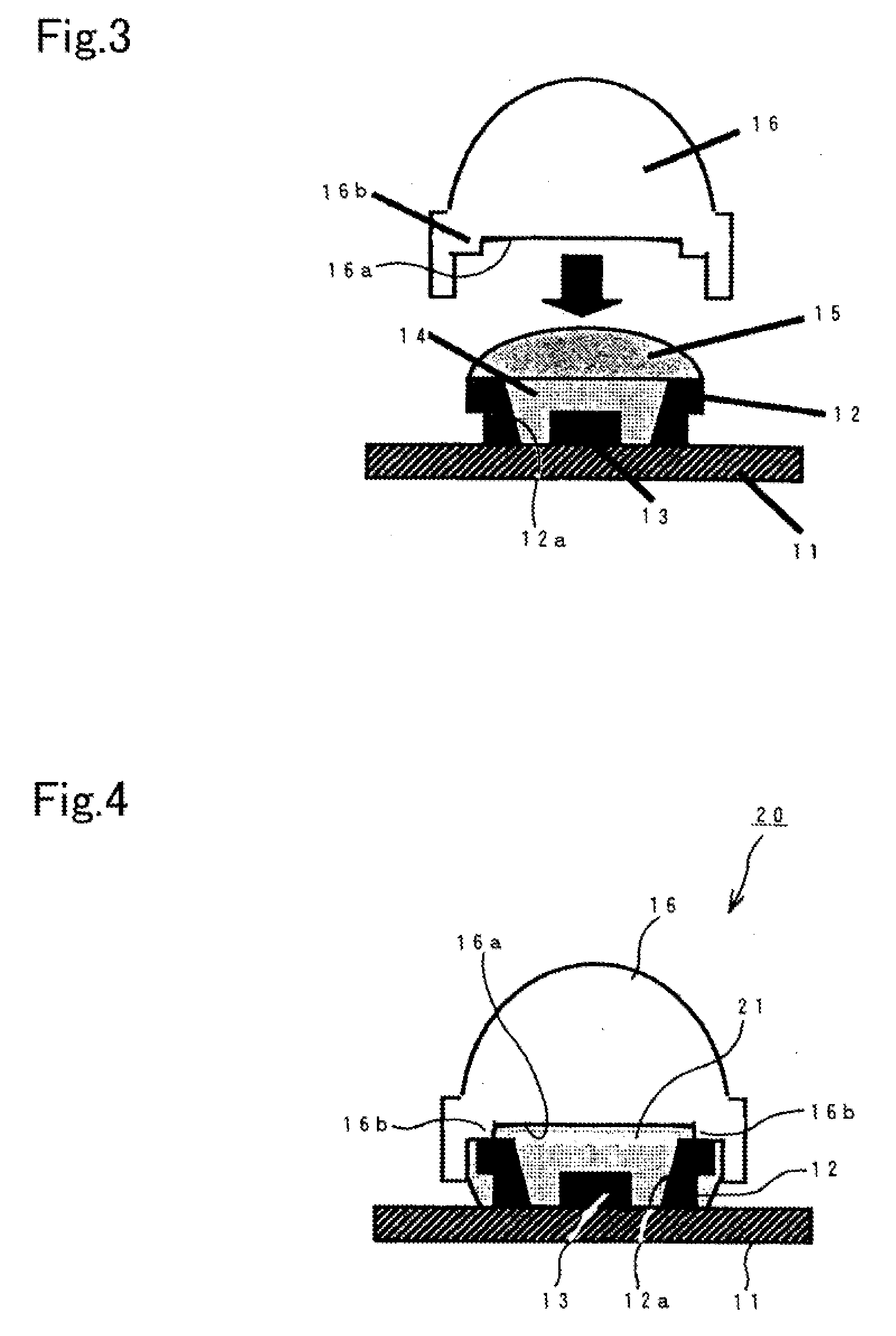
[0038]The first exemplary embodiment of the disclosed subject matter will now be described in detail with reference to FIG. 1 and FIG. 2. FIG. 1 is a cross-sectional view of a first exemplary embodiment made in accordance with principles of the disclosed subject matter and FIG. 2 is a bottom view showing an optical lens of the semiconductor light-emitting device shown in FIG. 1.

[0039]The semiconductor light-emitting device 10 can include: a base board 11 having a pair of chip mounting portions 11a; a reflector 12 that is formed in a substantially tubular shape with a cavity 12a, and disposed on the base board so as to enclose the pair of chip mounting portions 11a in the cavity 12a; a semiconductor light-emitting chip 13 that is mounted on the pair of chip mounting portions 11a, which are exposed on a bottom surface of the cavity 12a; an encapsulating resin 14 disposed in the cavity 12a of the reflector 12; a spacer 15 disposed over the reflector 12 that includes the encapsulating r...


PUM


Abstract

A reliable semiconductor light-emitting device and a method for manufacturing the same can be provided in which peeling can be prevented in a phase boundary, and optical axis positional errors between the optical lens and a semiconductor light-emitting chip can be reduced or prevented. The semiconductor light-emitting device can include a base board having at least one chip, a reflector fixed on the base board so as to enclose the chip, and an encapsulating resin disposed in the reflector. An optical lens can include a concave-shaped cavity that has an inner corner surface having a plurality of convex portions thereon. The optical lens can be located adjacent the reflector by contacting the lens with a top surface of the reflector so as to enclose the reflector. A spacer that is disposed between the concave-shaped cavity and the reflector can ease a stress that is generated due to temperature changes.

Description


Claims


Application Information

Patent Timeline
Owner STANLEY ELECTRIC CO LTD
Why Eureka
Try Eureka