Jamming signal detector
Inactive Publication Date: 2007-11-22
TMC DESIGN CORP
View PDF6 Cites 9 Cited by
- Summary
- Abstract
- Description
- Claims
- Application Information
AI Technical Summary
Benefits of technology
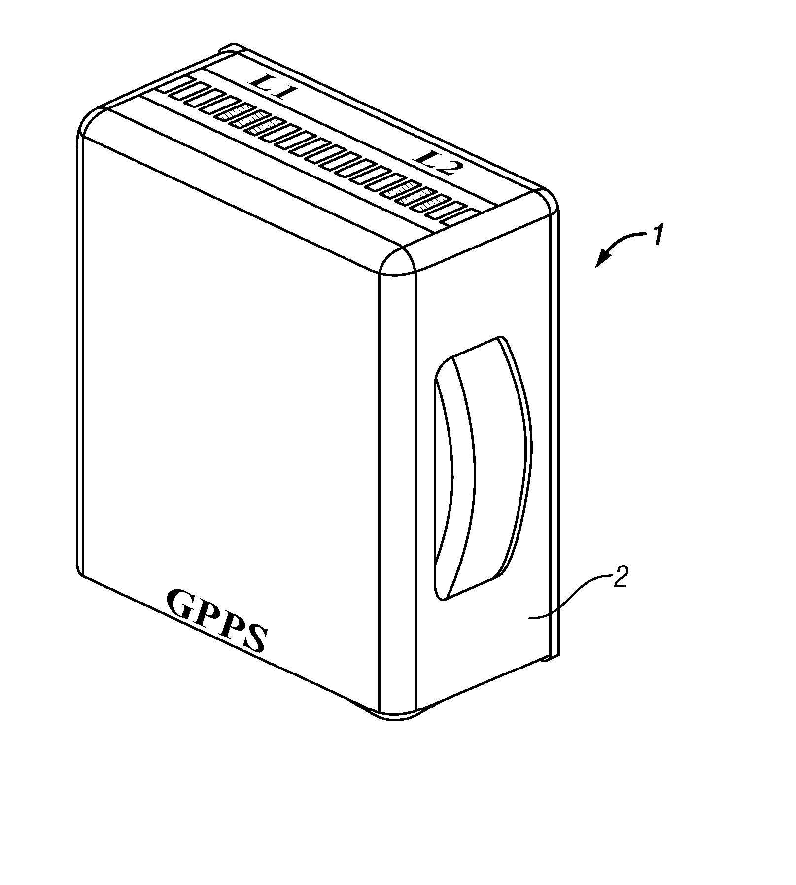
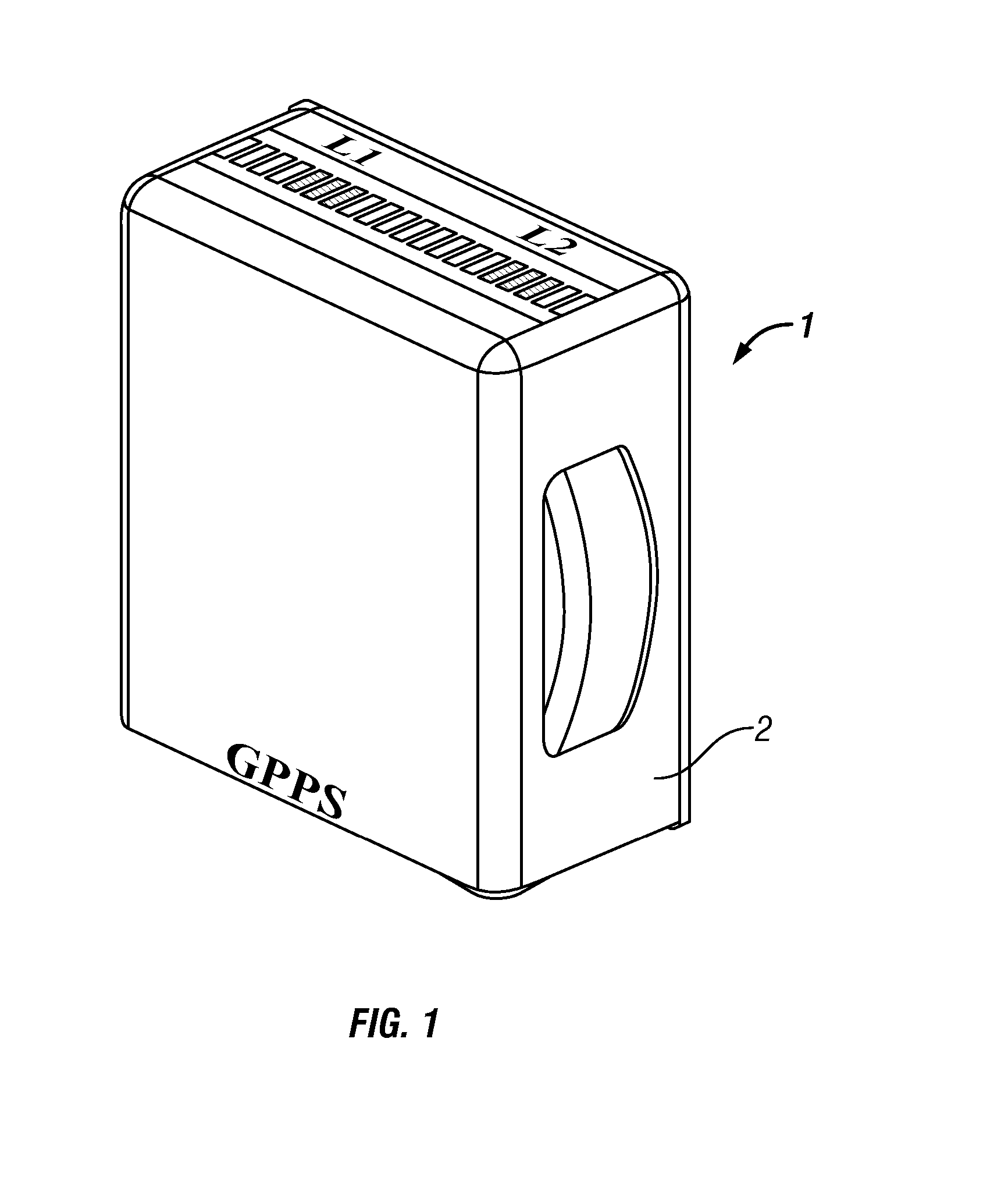
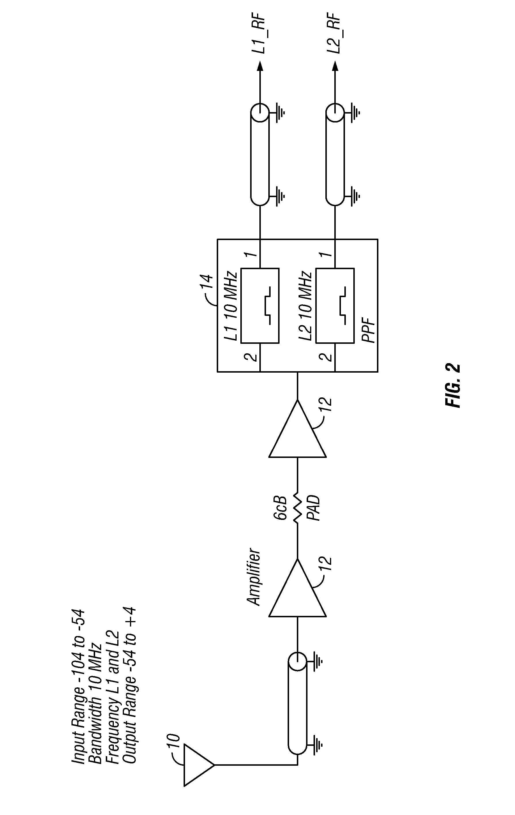
[0008] The apparatus in accordance with the present invention detects (GPS) jamming signals with the use of a sensitive receiver that is optimized to detect and measure interference at both GPS frequencies L1 and L2, or at other predetermined frequencies. Furthermore, with the use of a directional antenna, the present invention preferably gives an indication as to the direction of the interference, thus providing crucial intelligence to the user which can be used in determining a course of action.
Problems solved by technology
Loss of a GPS signal is becoming an ever increasing problem for users, that must be addressed.
Either unintentional interference caused by increased use of the radio frequency (RF) spectrum or intentional jamming has resulted in many reported cases where the ability to use a GPS signal has been denied or significantly degraded.
Typically, the user realizes that his / her GPS is not operating properly at some critical moment when either, time, location or direction is needed to perform a mission.
Method used
View moreImage
Smart ImageViewing Examples

Examples
example
[0033] In an embodiment, the design specifications of the present invention preferably include:
Frequency of Operation:L1 (1.57542 GHz) and L2 (1.2276 GHz)Minimum Detect Level:−100 dBmDynamic Range:60 dBBandwidth of each channel:10 MHzIndication of Interference:3 LevelsSize & Power:(approx size of cigarette pack)Power:AA Batteries
[0034] Those skilled in the art will readily recognize that numerous aspects of these specifications can be altered and desirable results will still be produced.
Login to view more PUM
 Abstract
The present invention relates to an apparatus and a method for detecting and displaying the existence of a jamming signal. An antenna receives a signal on a predetermined frequency, and an amplifier receives and amplifies the signal from the antenna. A microprocessor determines the existence and magnitude of the jamming signal related to the predetermined frequency and processes an output to a display device to display the existence of the jamming signal to a user.
Description
CROSS-REFERENCE TO RELATED APPLICATIONS [0001] This application claims priority to and the benefit of the filing of U.S. Provisional Patent Application Ser. No. 60 / 783,514, entitled “GPS Signal Jamming Detector”, filed on Mar. 17, 2006, and the specification thereof is incorporated herein by reference.BACKGROUND OF THE INVENTION [0002] 1. Field of the Invention (Technical Field) [0003] The present invention relates to an apparatus and method which provides notification when global positioning system (GPS) signals are being jammed. Particularly, the present invention relates to a small and mobile apparatus which can be worn by a user and which either flashes, vibrates, provides an audible or visible indication, or combinations thereof, when it detects a jamming signal. [0004] 2. Description of Related Art [0005] Loss of a GPS signal is becoming an ever increasing problem for users, that must be addressed. People are becoming more and more dependent upon equipment that directly or ind...
Claims
Login to view more Application Information
Patent Timeline
 IPC IPC(8): H04B7/185G01S19/11G01S19/05G01S19/21G01S19/29G01S19/46
CPCG01S19/21H04K3/20H04B1/1027G01S19/35H04K3/22
Inventor HAM, CHRISTOPHER V.SCOUGHTON, TROY E.
Owner TMC DESIGN CORP
- R&D Engineer
- R&D Manager
- IP Professional
Why Eureka
- Industry Leading Data Capabilities
- Powerful AI technology
- Patent DNA Extraction
Try Eureka
Browse by: Latest US Patents, China's latest patents, Technical Efficacy Thesaurus, Application Domain, Technology Topic.
© 2024 PatSnap. All rights reserved.Legal|Privacy policy|Modern Slavery Act Transparency Statement|Sitemap