Optical cable shield layer connection

a shield layer and optical cable technology, applied in the field of optical cables, can solve the problems of high cost and/or hazardous materials, high assembly time, and damage to heating

Active Publication Date: 2007-11-22
SUBCOM LLC
View PDF10 Cites 67 Cited by
  • Summary
  • Abstract
  • Description
  • Claims
  • Application Information

AI Technical Summary

Problems solved by technology

Such existing processes may involve extensive assembly time, pot

Method used


Image

  • Optical cable shield layer connection
  • Optical cable shield layer connection
  • Optical cable shield layer connection

Examples


Embodiment Construction

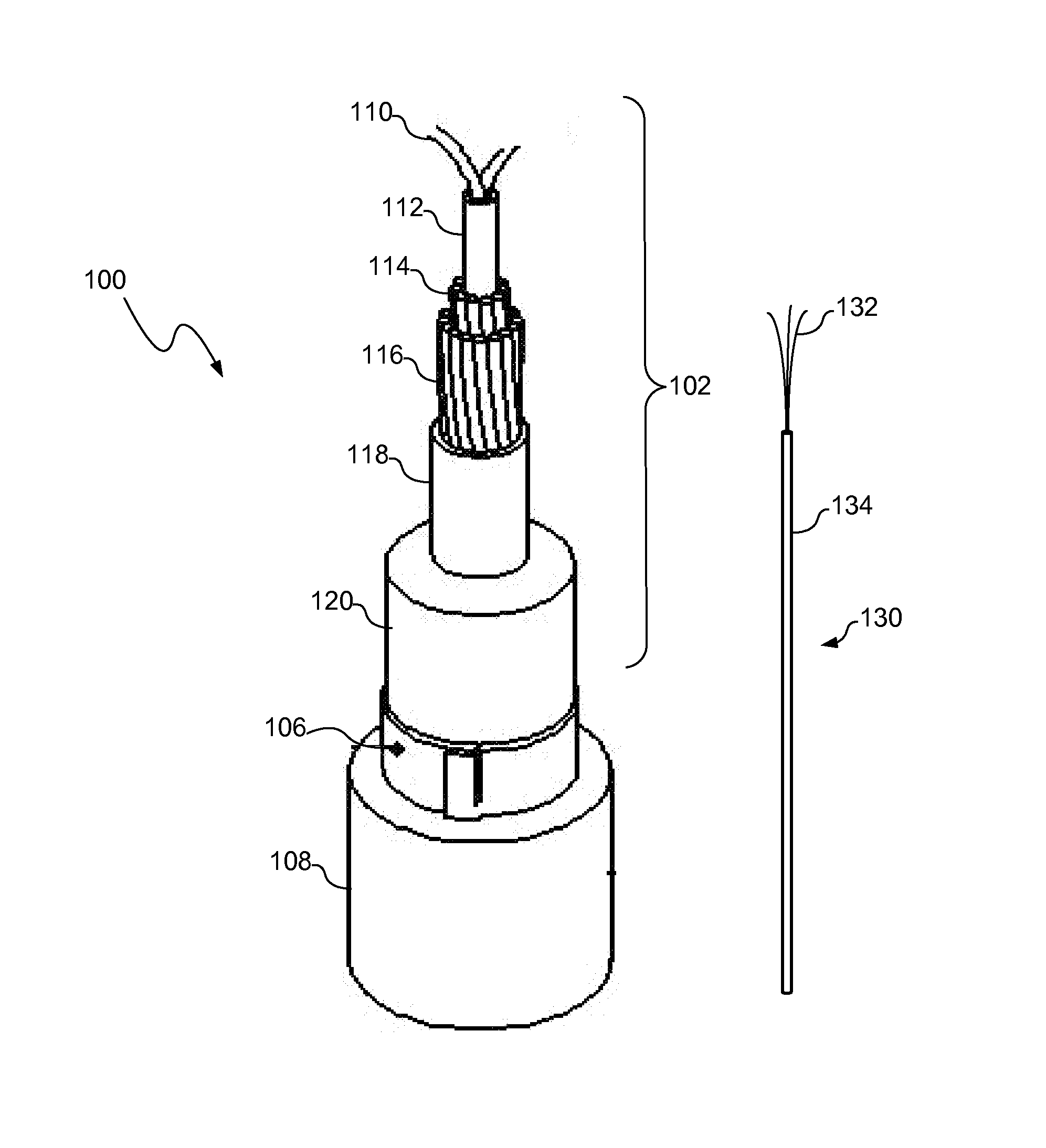
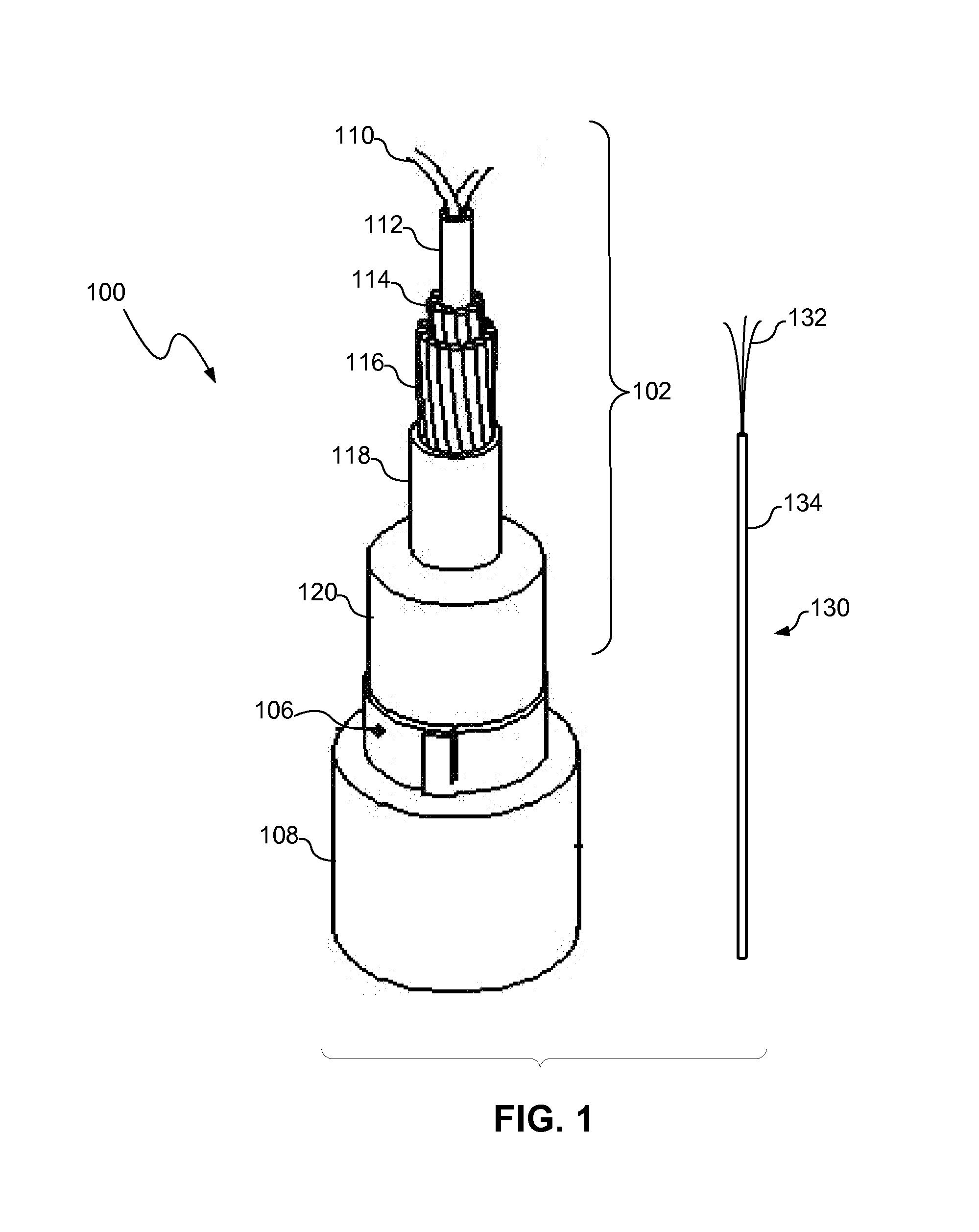
[0008] An optical cable shield layer connection may include a wire electrically connected to a shield layer of an optical cable. The optical cable shield layer connection may also be sealed to prevent leak paths. The optical cable shield layer connection may be made when coupling the optical cable to a device or another cable, for example, using a universal joint such as the Millennia® Joint available from Tyco Telecommunications (US) Inc. The wire may provide a ground path from the shield layer or a continuity path from the shield layer to another optical cable.

[0009] Referring to FIG. 1, an optical cable 100, consistent with one embodiment of the present invention, may include a cable core portion 102, at least one shield layer 106 and at least one outer sheath 108. The shield layer 106 of the optical cable 100 may be connected to a wire 130 including one or more conductors 132 (e.g., strands). The wire 130 may also include one or more insulation layers 134 around the conductor(s...


PUM


Abstract

An optical cable shield layer connection may include a wire electrically connected to a shield layer of an optical cable. The optical cable shield layer connection may also be sealed, for example, to prevent leak paths. The optical cable shield layer connection may be made when coupling the optical cable to a device or another cable, for example, using a universal joint such as the Millennia® Joint available from Tyco Telecommunications (US) Inc. The wire may provide a ground path from the shield layer or a continuity path from the shield layer to another optical cable.

Description

TECHNICAL FIELD [0001] The present invention relates to optical cables and more particularly, to a system and method for establishing an electrical connection to a shield layer of an optical cable. BACKGROUND INFORMATION [0002] Optical fibers may be used as transmission paths for optical signals in communications networks. Such optical fibers often must extend across many miles and large bodies of water. To protect the optical fibers, particularly in an undersea or submarine environment, the optical fibers may be included in an optical cable that provides many layers of protection. An undersea or submarine optical cable may include, for example, layers of strength members, tubing, insulation, shielding, and sheaths depending upon the system environmental conditions. [0003] Optical cables sometimes must be coupled to other cables or to other devices (e.g., to repeaters or branching units). To repair an optical cable, for example, one segment of the optical cable may be coupled to ano...

Claims


Application Information

Patent Timeline
IPC IPC(8): G02B6/44
CPCG02B6/3816G02B6/3817G02B6/4416G02B6/4475H01R43/005H01R4/72H01R9/034H01R9/0512H01R13/523H01R4/48H01R13/65914
Inventor STIX, ROBERT K.MENDEZ, JEREMIAH A.JACKSON, JAMESKORDAHI, MAURICE
Owner SUBCOM LLC
Why Eureka
Try Eureka