Wood and Plastic Screw

a technology of plastic screw and wood, which is applied in the direction of screws, nuts, bolts, etc., can solve the problems of inability to produce flank angles and inability to produce exact angles, etc., and achieve the effects of less manufacturing complexity, increased displacement, and relatively simple manufacturing

Inactive Publication Date: 2007-11-22
BERNER
View PDF13 Cites 39 Cited by
  • Summary
  • Abstract
  • Description
  • Claims
  • Application Information

AI Technical Summary

Benefits of technology

[0006] According to the invention, this is obtained by a wood or plastic screw that has a head, an essentially cylindrical shank, a tip, and a thread extending along the shank as far as into a tip region. The thread comprises a tip-side and a head-side flank, where a head-side flank angle is larger than a tip-side flank angle. The tip-side flank angle remains approximately constant in a shank region and in the tip region whereas the head-side flank angle in the tip region is larger than that in the shank region. A flank angle is an angle enclosed by a corresponding flank with a radial plane to a center axis of the screw. In comparison with document EP 0 504 782 B1, the invention uses a different approach in which the screw thread in the tip region is in fact more asymmetrical than in the shank region. Furthermore, the manufacture is relatively simple since the tip-side flank angle remains constant in approximately the entire threaded region. However, the head-side flank angle in the tip region becomes larger than that in a flank region, i.e. there is more room in the tip region for material displaced during the manufacture of the screw, which renders the manufacture less complex to keep the required tolerances. During the screwing in of a dowel, the flank geometry provides for an increased displacement and thus for improved extraction values.

Problems solved by technology

When manufacturing screws, the flank angles cannot be produced to an exact angular degree and it is also not possible to produce a flank angle that is uniform along the entire thread length.

Method used


Image

  • Wood and Plastic Screw
  • Wood and Plastic Screw

Examples


Embodiment Construction

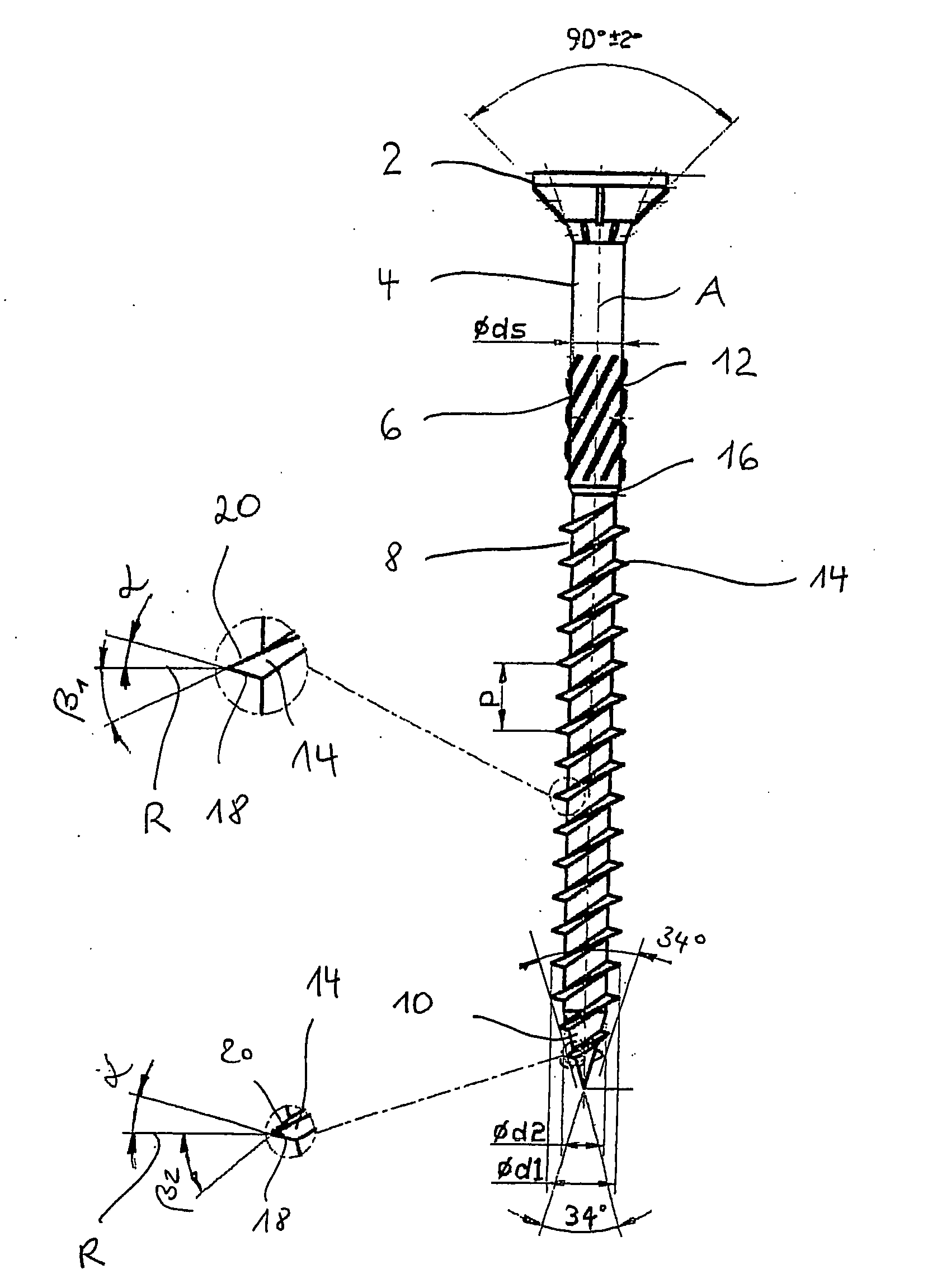
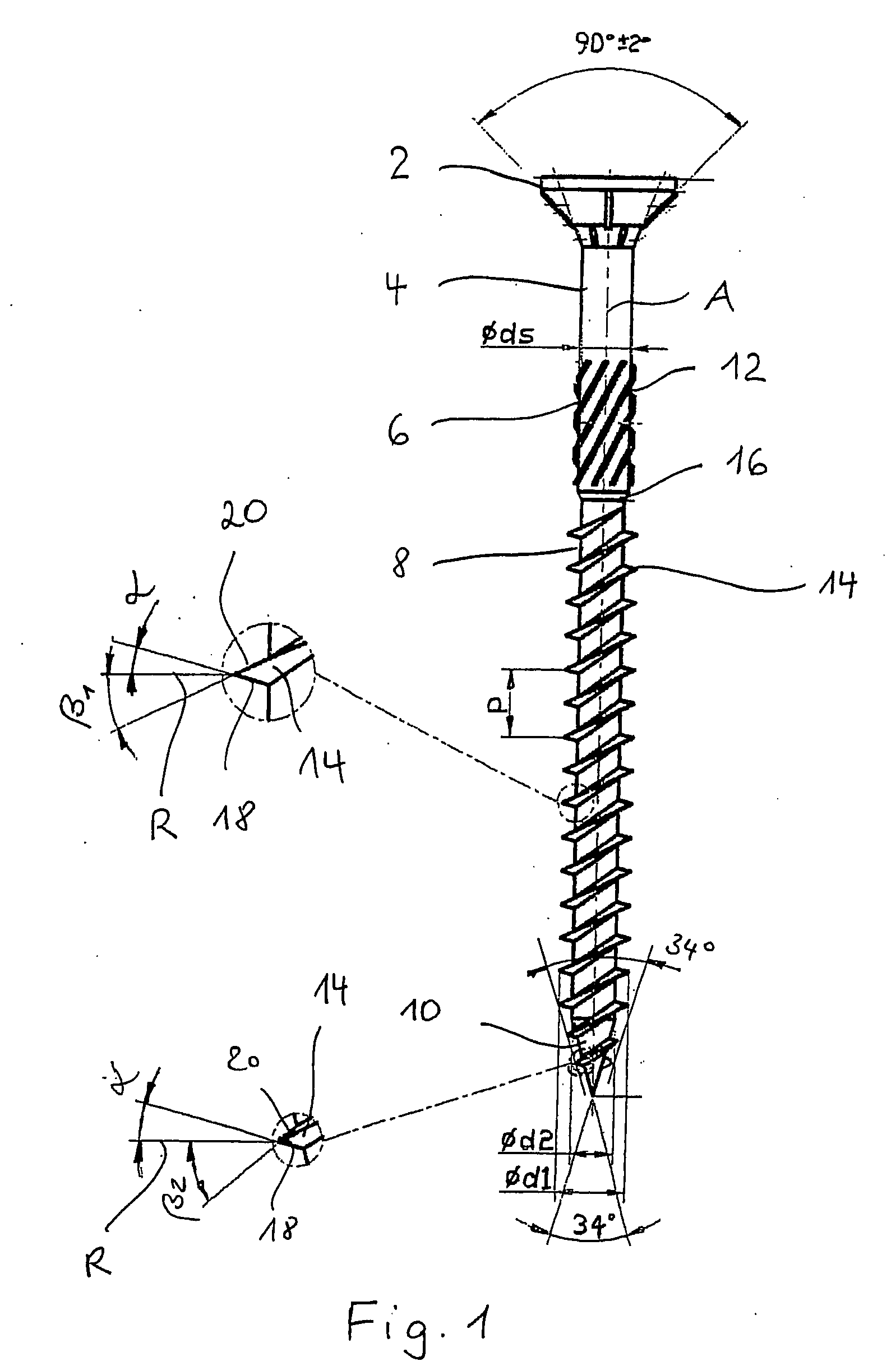
[0016] The screw shown in FIG. 1 for screwing in solid wood, chipboards, dowels etc. is made of metal and has a head 2, a shank which is to be divided up essentially in three regions 4, 6 and 8, and a tip region 10. The region 4 of the shank is configured cylindrically and has neither a thread nor other projections. The adjoining shank region 6 is provided with milling ribs 12. Regions 4 and 6 of the shank have the same diameter ds, (in the region 6, this diameter ds, is a core diameter). A two-start thread 14, which has a pitch p and extends as far as into the tip region 10, has a starting point in the region 8. Here, the core diameter d2 is smaller than the diameter ds such that the regions 8 and 6 are separated from each other by a shoulder 16.

[0017] The thread 14 has a tip-side lower flank 18 and a head-side upper flank 20. A tip-side flank angle α in the region 8 of the shank is approximately as large as that in the tip region 10, and is approximately 15°. The tip-side flank a...


PUM

PropertyMeasurementUnit
flank angleaaaaaaaaaa
angleaaaaaaaaaa
flank angleaaaaaaaaaa

Abstract

A wood and plastic screw has an essentially cylindrical shank, a tip, and a thread extending along the shank as far as into a tip region. The thread comprises a tip-side and a head-side flank, with a head-side flank angle being larger than a tip-side flank angle. The tip-side flank angle remains approximately constant in a shank region and in the tip region whereas the head-side flank angle in the tip region is larger than that in the shank region.

Description

RELATED APPLICATIONS [0001] The application is a U.S. national phase application of PCT / EP2006 / 003710, which was filed on Apr. 21, 2006, claiming priority to German Patent Application 20 2005 06 493.9, which was filed on Apr. 4, 2005.BACKGROUND OF THE INVENTION [0002] The invention relates to a wood and plastic screw. [0003] Wood screws, which also include chipboard screws, are intended for being screwed into a work piece as easily and quickly as possible while still having a high extraction resistance. Plastic screws are screwed into dowels and are intended to provide a high pressing in of the dowel, and thus for a high extraction resistance of the dowel. [0004] A screw in which a screw thread in a region of the screw tip, in comparison with a shank region, has a less asymmetrical to symmetrical shape, is known from document EP 0 504 782 B1. This screw is to be distinguished by a low screwing resistance, a large stripping torque and good extraction values. [0005] The invention prov...

Claims


Application Information

Patent Timeline
Patent Type & Authority Applications(United States)
IPC IPC(8): F16B35/00F16B25/00F16B33/02
CPCF16B25/00F16B25/0015F16B33/02F16B25/0057F16B25/0047
Inventor RUNGE, ERICHLOEFFLER, RALF
Owner BERNER
Why Eureka
Try Eureka