Methods and apparatus for vertically orienting substrate processing tools in a clean space

Active Publication Date: 2007-11-22
FUTRFAB
View PDF5 Cites 23 Cited by
  • Summary
  • Abstract
  • Description
  • Claims
  • Application Information

AI Technical Summary

Benefits of technology

[0010] Accordingly, the present invention provides a novel design for processing fabs which arrange a clean room to allow processing tools to reside in both vertical and horizontal dimensions relative to each other and in some embodiments with their tool bodies outside of, or on the periphery of, a clean space of the fabricator. In such a design, the tool bodies can be removed and replaced with much greater ease than is the standard case. The design also anticipates the automated transfer of substrates inside a clean space from a tool port of one tool to another. The substrates can

Problems solved by technology

However, known cleanroom design has disadvantages and limitations.
For example, as the size of tools has increased and the dimensions of cleanrooms have increased, the volume of cleanspace that is controlled has concomitantly increased.
In addition, the size of currently known fabricator processing tools and their floor space mounting surfaces and utility connections result in fabs with ever increasing floor space footprints.
Consequently, the cost of building the cleanspace

Method used


Image

  • Methods and apparatus for vertically orienting substrate processing tools in a clean space
  • Methods and apparatus for vertically orienting substrate processing tools in a clean space
  • Methods and apparatus for vertically orienting substrate processing tools in a clean space

Examples


Example

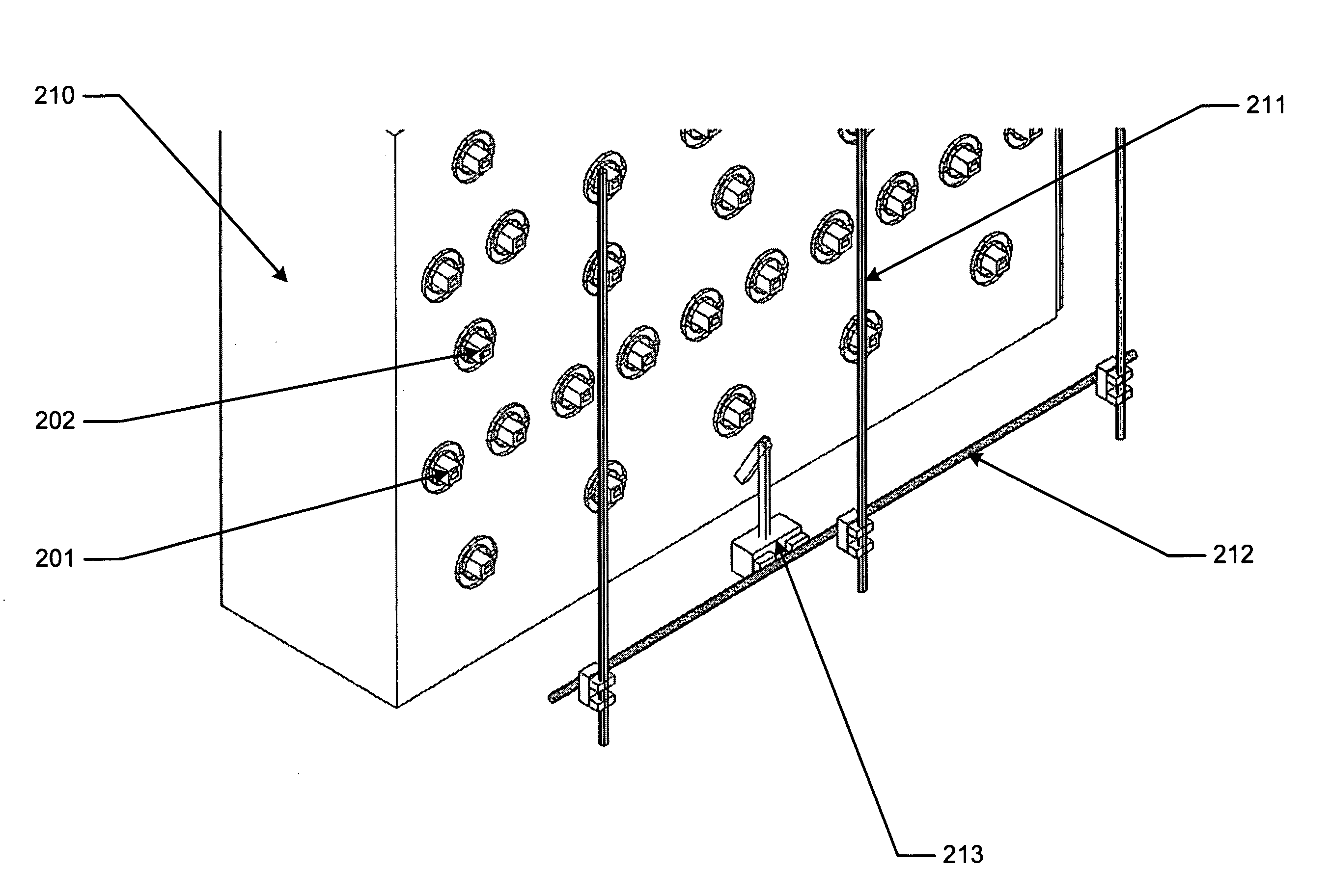
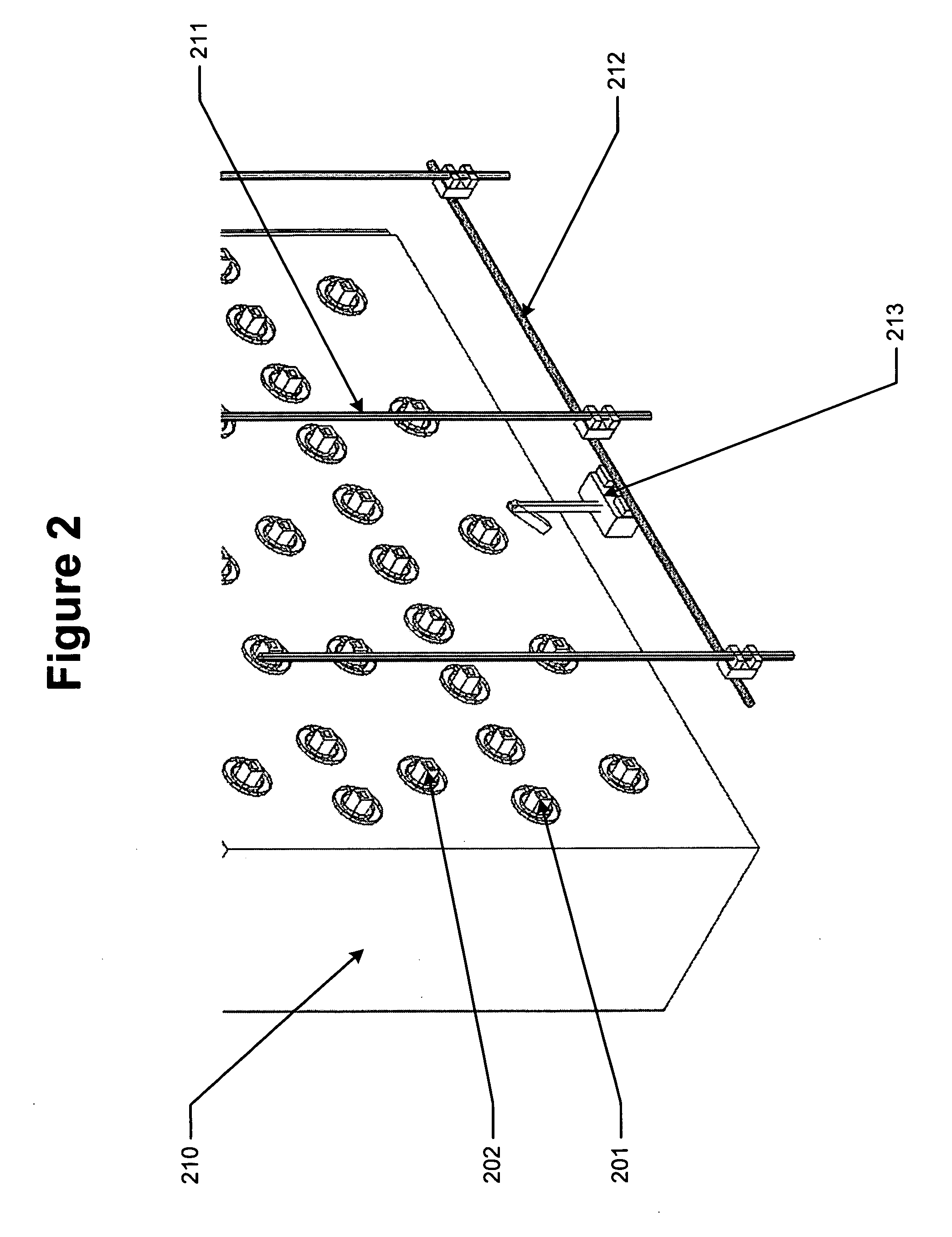
[0023] The present invention relates to methods and apparatus which enable the positioning of processing tools in a fab in both vertical and horizontal dimensions. According to the present invention, a portion of a tool used to process a material is accessible from within a cleanspace in which the material is processed and an additional portion of the processing tool remains outside of the cleanspace environment in which the material is processed. In addition, the present invention provides for methods and apparatus to facilitate installation, removal and maintenance of the tools used to process the material.

[0024] Reference will now be made in detail to different aspects of some preferred embodiments of the invention, examples of which are illustrated in the accompanying drawings. Wherever possible, the same reference numbers will be used throughout the drawings to refer to the same or like parts. A Glossary of Selected Terms is included at the end of this Detailed Description.

[0...


PUM


Abstract

The present invention provides various aspects of support for a fabrication facility capable of routine placement and replacement of processing tools in at least a vertical dimension relative to each other.

Description

CROSS REFERENCE TO RELATED APPLICATIONS [0001] This application claims priority to the Provisional Application Ser. No. 60 / 596,343, filed Sep. 18, 2005 and entitled: Specialized Methods for Substrate Processing for a Clean Space Where Processing Tools are Vertically Oriented. The contents of each are relied upon and incorporated by reference herein.FIELD OF THE INVENTION [0002] The present invention relates to apparatus and methods which support fabricators with routinely replaceable processing tools vertically arranged in one or more cleanspaces. BACKGROUND OF THE INVENTION [0003] A known approach to cleanspace-assisted fabrication of materials such as semi-conductor substrates is to assemble a manufacturing facility as a “cleanroom.” In such cleanrooms, processing tools are arranged to provide aisle space for human operators or automation equipment. Exemplary cleanroom design is described in: “Cleanroom Design, Second Edition,” edited by W. Whyte, published by John Wiley & Sons, 1...

Claims


Application Information

Patent Timeline
IPC IPC(8): B65H29/00
CPCH01L21/67178H01L21/67745H01L21/67276
Inventor FLITSCH, FREDERICK A.
Owner FUTRFAB
Why Eureka
Try Eureka