True 3D cone-beam imaging method and apparatus

a cone beam and imaging method technology, applied in tomography, instruments, nuclear engineering, etc., can solve the problems of the most complex and expensive computation in cone beam imaging, and achieve the effects of accurate determination, better sampling performance, and improved image quality

Inactive Publication Date: 2005-03-08
MIT TECH LICENSING OFFICE
View PDF16 Cites 27 Cited by
  • Summary
  • Abstract
  • Description
  • Claims
  • Application Information

AI Technical Summary

Benefits of technology

Source orbits disclosed herein are aimed at offering better sampling performance in the Radon space and consequently better image qualities in the reconstruction. A new family of source orbits disclosed herein is the biquardatic source curve. The parameters of the biquadratic source curve can be tuned in accordance with the dimension of the scanned object. Another benefit of using the biquadratic curve is that it has at most four intersections with a plane in the three-dimensional space. We are able to give an analytic procedure for deciding the number of intersections between a specified source orbit and an arbitrary plane in the three-dimensional space; accurate determination of the multiplicity function is important for cone-beam reconstruction because it determines the weights of each plane passing by a particular source point along the source orbit.
The disclosed technique allows simple and systematic approach to cone-beam tomographic reconstructions in general. A number of different source-detector configurations and orientations, as well as a large family of scanning orbits satisfying the so-called data sufficiency condition can be successfully treated in a unified reconstruction framework with greater ease, simplicity and improved efficiency. For example, methods involving helical source orbits are described herein, and adaptations made to treat the truncated helical cone-beam reconstruction are also described.

Problems solved by technology

In terms of the reconstruction procedure, the most complex and expensive computation in cone-beam imaging lies in the backprojection-differentiation operation.

Method used


Image

  • True 3D cone-beam imaging method and apparatus
  • True 3D cone-beam imaging method and apparatus
  • True 3D cone-beam imaging method and apparatus

Examples


Embodiment Construction

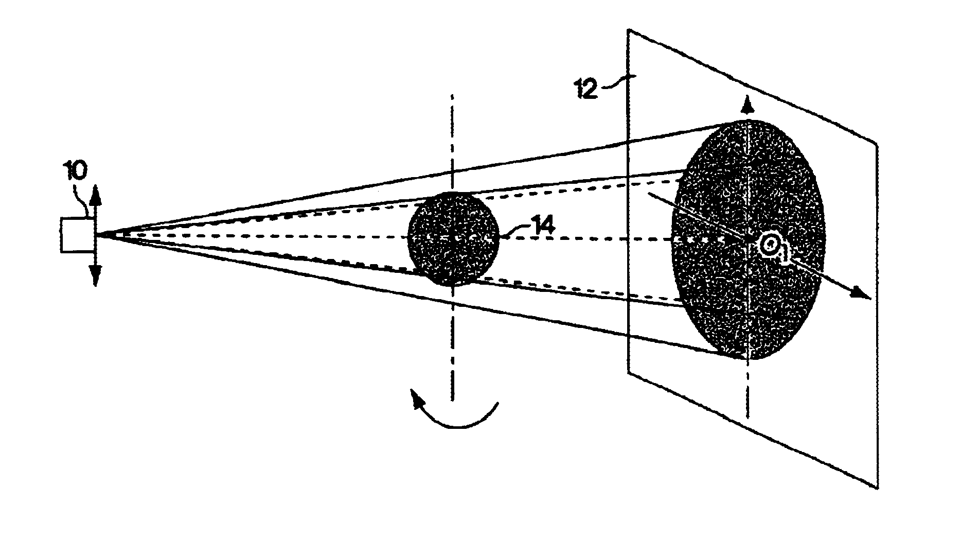
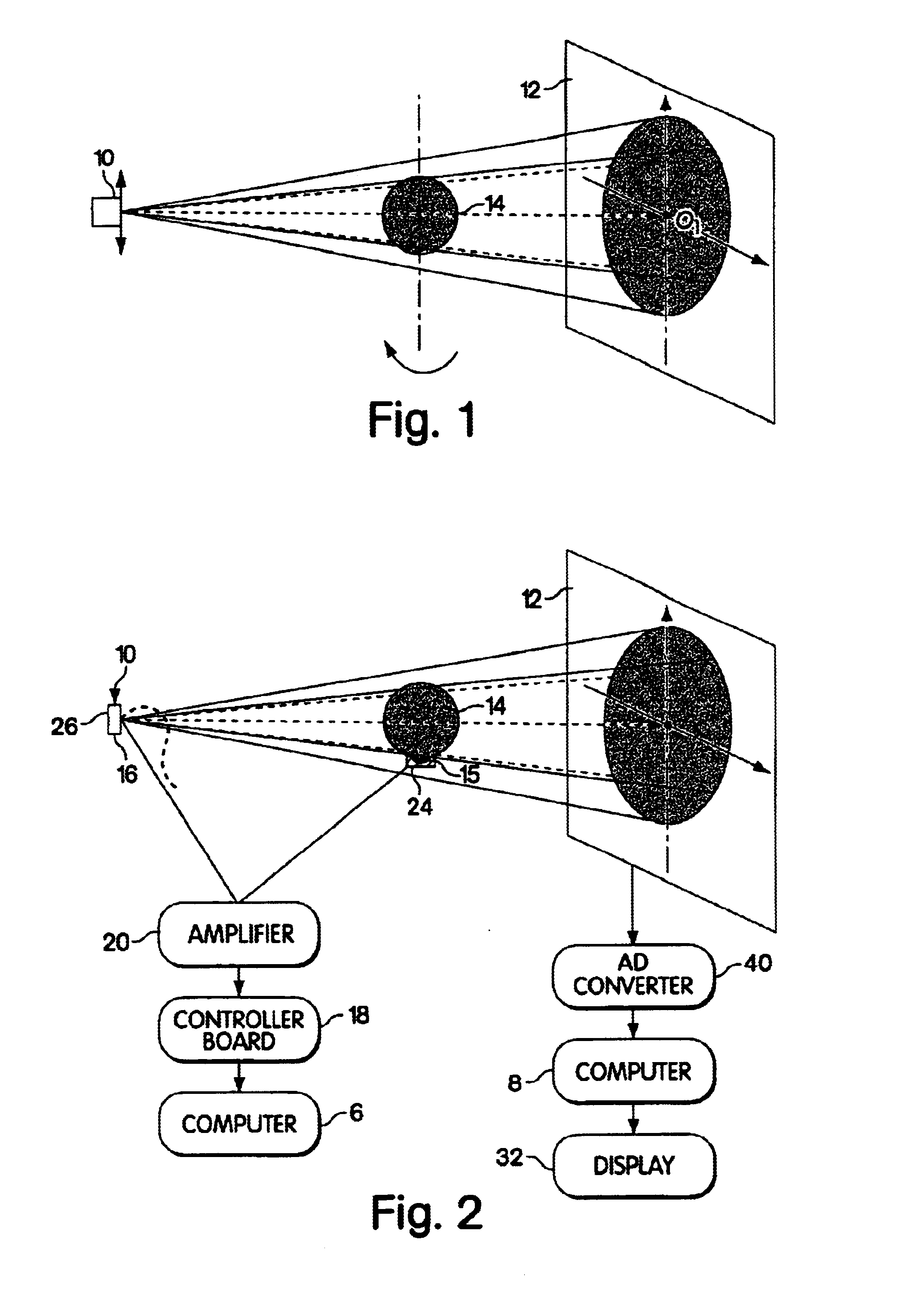
FIG. 2 illustrates a suitable apparatus for generating and detecting a plurality of cone-beam projections from a radiation source as well as recovering the three-dimensional attenuation map inside the object being scanned from the collected cone-beam projection measurement. Specifically, the physical hardware of a cone-beam imaging system comprises a radiation source 10, a two-dimensional area detector 12 that receives the attenuated rays emitting from the point source and passing by the object 14, at least two motors 15 and 16 (the source and detector can be controlled by a single motor or separately by two different motors), which are accountable for the relative movement between the source-detector system and the object 14, an analog-to-digital converter 40 that converts the cone-beam signals detected by the area detector into a digital format that enters the computer system 8 as input, and the computer system 8, which stores, processes the converted cone-beam data to reconstruct...


PUM


Abstract

A three-dimensional image of an object scanned with a plurality of cone-beam projections from a number of source positions is reconstructed using a method wherein intermediate transform functions are obtained from two-dimensional images of radiation attenuation in the scanned object. The intermediate transform functions are then filtered over a set of parallel planes using a moving-frame technique. The second-order radial derivative of the Radon transform can then be backprojected to generate an intermediate, locally-reconstructed, three-dimensional image. After repetition of this process, the plurality of intermediate, locally reconstructed, three-dimensional images are summed to obtain an ultimate, reconstructed, three-dimensional image of the object. In particular embodiments, the source and detector are displaced along helical paths and radiation scans of the object are taken at multiple positions along the paths.

Description

BACKGROUNDCone-beam computerized tomography (CT) reconstructs the absorption function of a three-dimensional object from a set of cone-beam projections. Such a system uses an area detector to receive rays emitted from an X-ray point source and attenuated by partial absorption in the object through which they pass. As in traditional (i.e., planar) CT, the source 10 and the detector 12 are placed on opposite sides of the object 14 being scanned (see FIG. 1). Rays contributing to an image on the detector surface form a cone with the X-ray source 10 at the apex. From the X-ray radiance value recorded at a point on the area detector 12, one can compute the integral of attenuation along the ray from the X-ray source 10 to the given point on the detector 12.As the source-detector 10 / 12 pair undergoes a simultaneous rotation and translation around the object 14, a plurality of two-dimensional cone-beam images projected from various source positions can be acquired and used to reconstruct th...

Claims


Application Information

Patent Timeline
Patent Type & Authority Patents(United States)
IPC IPC(8): G06T11/00A61B6/03
CPCA61B6/027G06T11/006A61B6/032A61B6/4085Y10S378/901G06T2211/421
Inventor YANG, XIAOCHUN
Owner MIT TECH LICENSING OFFICE
Why Eureka
Try Eureka