
Apparatus and method for loading and delivering a stent

a technology for delivering stents and apparatuses, which is applied in the field of methods and systems for loading and delivering radially distensible stents, can solve the problems of complex assembly of such delivery systems, affecting the quality of life of stents, and affecting the quality of stents,

Inactive Publication Date: 2007-11-22
BOSTON SCI SCIMED INC
View PDF13 Cites 364 Cited by
  • Summary
  • Abstract
  • Description
  • Claims
  • Application Information

AI Technical Summary

Benefits of technology

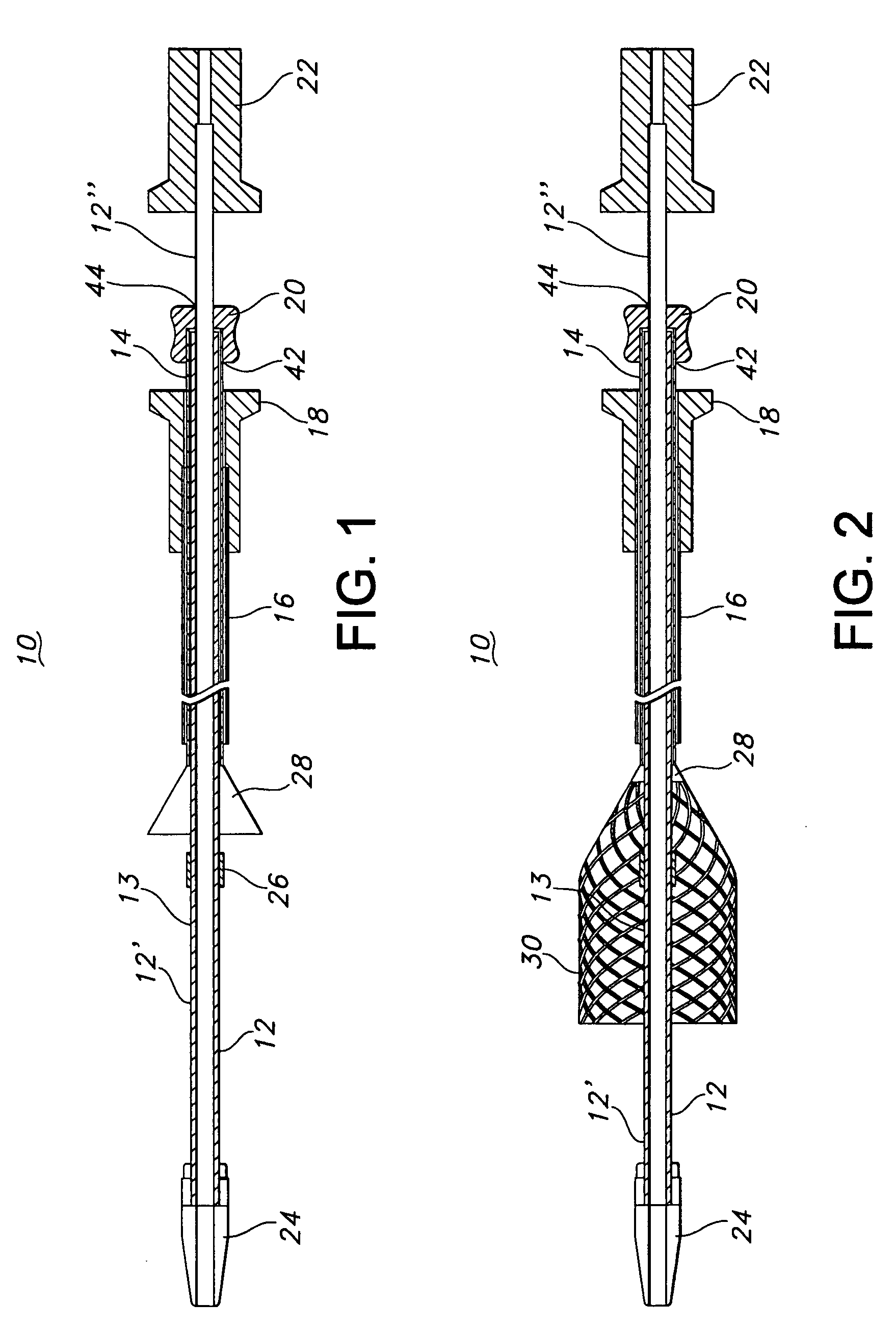
The present invention provides a method and system for delivering a stent into a body lumen using a stent loading and deployment device. The device includes an outer elongate tubular member, an inner elongate tubular member, and a stent loading member. The stent loading member is a slidable device that can hold and release the stent. The stent is inserted into the device and can be disengaged from the stent loading member for deployment. The invention allows for easy and secure loading of stents into the delivery and deployment device, making the process easier and more efficient.

Problems solved by technology

Although stent delivery systems are well-known in the art, the assembly of such delivery systems is often complicated.
Unlike most metallic self-expanding stents, the plastic ones have a tendency to permanently deform or lose some of their ability to self-expand when stored in a compressed state for a prolonged period of time.
However, such loading often involves numerous steps and requires the use of multiple components (e.g., tools and fixtures) that are not part of the stent delivery system.
Also, even with these added devices, the physician or user is often required to finish the loading process by pushing the stent into the delivery system by hand.
Loading a stent in this way is therefore often difficult, time-consuming and has the potential to damage the stent.

Method used


Image

  • Apparatus and method for loading and delivering a stent
  • Apparatus and method for loading and delivering a stent
  • Apparatus and method for loading and delivering a stent

Examples


Embodiment Construction

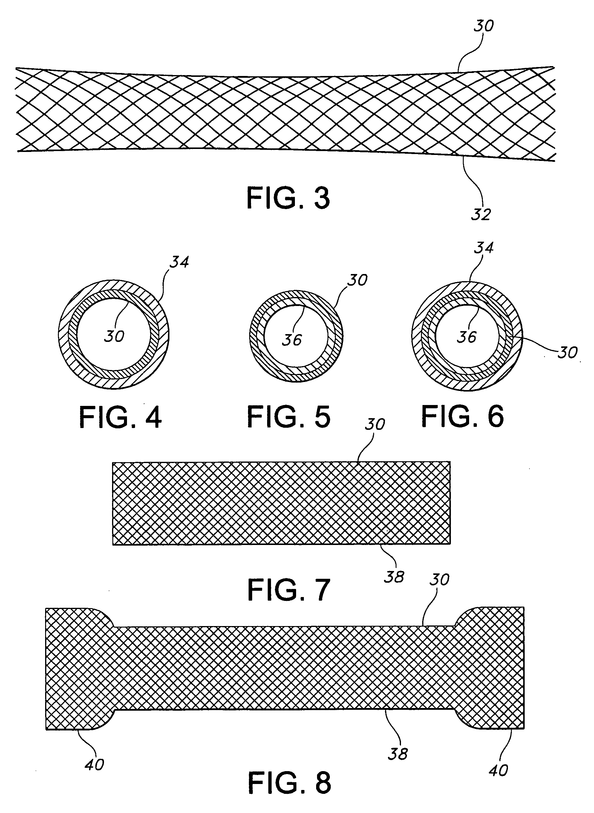
[0034]The present invention relates to an assembly and method for transporting and deploying a stent, or other intraluminary member as described herein, in a bodily passageway. The assembly is suited for medical applications (particularly, endoscopic therapy) in the gastrointestinal tract, the biliary tract, the urinary tract, and the respiratory tract. In particular, a preferred embodiment of the present invention is directed to an assembly and method for transporting, loading and delivering a self-expanding esophageal stent. The system allows the clinician or user to easily load a stent into a delivery system with minimal effort and without damaging the stent. The assembly in accordance with the present invention, however, could also be used in the neurological system (e.g., in the brain), the vascular system (e.g., in arteries or veins), in the cardiovascular system (e.g., in the heart) and in the like. Reference to bodily passageways may be to passageways in any of the aforement...


PUM


Abstract

A stent loading and deployment device includes an outer elongate tubular member having opposed proximal and distal ends and an inner elongate tubular member having opposed proximal and distal ends and slidably disposed within the outer tubular member. When the distal ends of the outer tubular member and the inner tubular member are axially aligned, a stent deployment region is defined there in between. The device further includes a stent loading member having opposed proximal and distal ends and slidably disposed between the outer tubular member and the inner tubular member. The distal end of the stent loading member is slidable to a distal position past the distal end of the outer tubular member for receiving a stent and is further slidable toward the proximal end of the outer tubular member to a location past the stent deployment region for disengagement of a stent from the stent loading member.

Description

FIELD OF THE INVENTION[0001]This invention relates to a method and system for transporting, loading and delivering a stent, as well as stent delivery assemblies. More particularly, this invention relates to methods and systems for loading and delivering radially distensible stents, including polymeric and non-polymeric stents.BACKGROUND OF THE INVENTION[0002]An intraluminary prosthesis is a medical device used in the treatment of diseased bodily lumens. One type of intraluminary prosthesis used in the repair and / or treatment of diseases in various body vessels is a stent. A stent is generally a longitudinal tubular device formed of biocompatible material which is useful to open and support various lumens in the body. For example, stents may be used in the bodily vessel, such as in the coronary or peripheral vasculature, esophagus, trachea, bronchi colon, biliary tract, urinary tract, prostate, brain, as well as in a variety of other applications in the body. These devices are implan...

Claims


Application Information

Patent Timeline
Patent Type & Authority Applications(United States)
IPC IPC(8): A61F2/06A61F2/82
CPCA61F2/95A61F2002/826A61F2002/9517A61F2002/9522A61F2/962A61F2002/9534A61F2002/9583A61F2/966A61F2002/9528A61F2/9517A61F2/9525A61F2/9522
Inventor HEADLEY, F. ANTHONYDAMARATI, JOHNLEANNA, GARY J.WOOD, MARK
Owner BOSTON SCI SCIMED INC
Learn More