Firearm barrel vibrational stabilizing device

Inactive Publication Date: 2007-11-29
FLETCHER KENT A
View PDF27 Cites 13 Cited by
  • Summary
  • Abstract
  • Description
  • Claims
  • Application Information

AI Technical Summary

Benefits of technology

[0010]An advantage of the present invention is improved firearm accuracy and uniformity from shot to shot.
[0011]Another advantage of the present invention is that for a rifle the device is preferably mounted to the barrel through the rifle's wooden forearm or stock, where the strongest vibrations typically occur.
[0012]Other objects, advantages and novel features, and further scope of applicability of the present invention will

Problems solved by technology

When firing a projectile through a firearm, vibrations in the firearm barrel are caused, which results in lower targeti

Method used


Image

  • Firearm barrel vibrational stabilizing device
  • Firearm barrel vibrational stabilizing device
  • Firearm barrel vibrational stabilizing device

Examples


Example

EXAMPLE 1

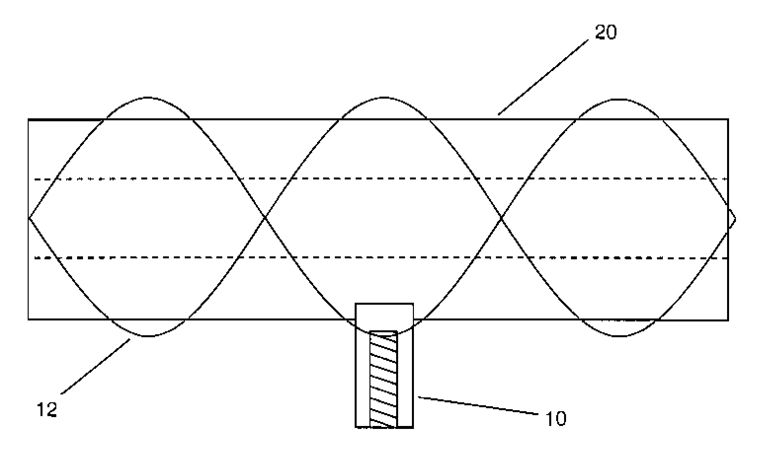
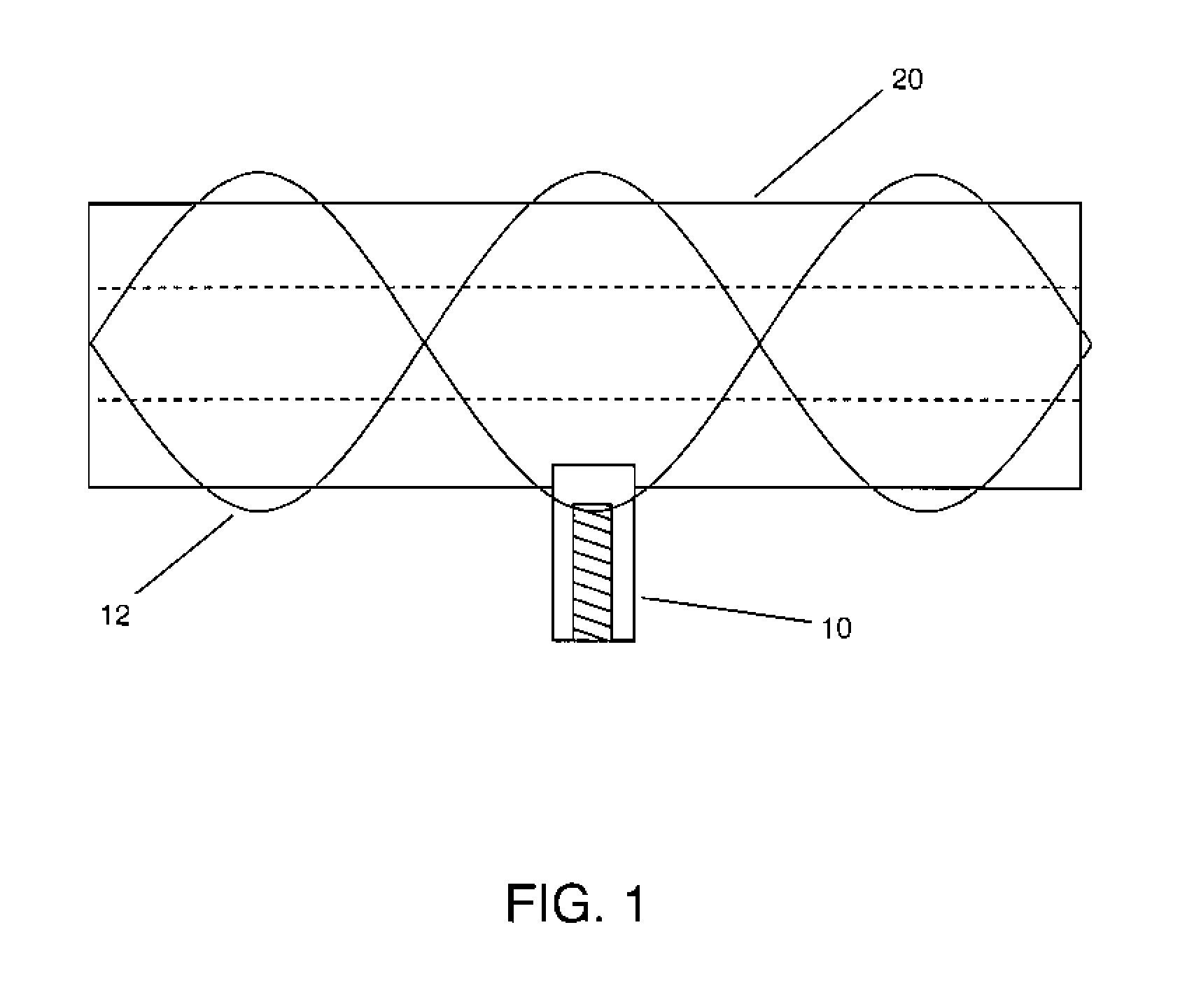
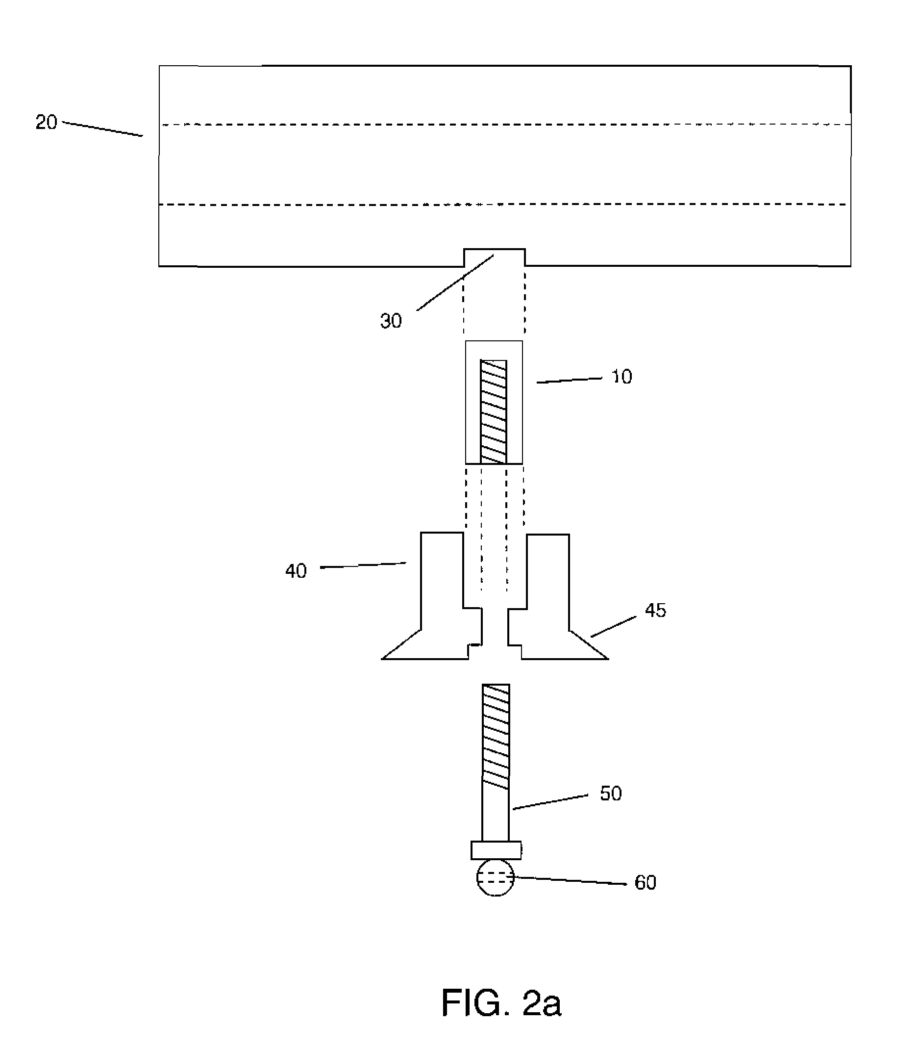
[0027]A .256 Newton custom 98 Mauser rifle equipped with the vibrational stability device of the present invention was test fired by a shooting and ballistics expert using a variety of ammunition at various loads. Referring to FIG. 2a, recess 30 was located 8.50″ from the muzzle. Post 10 was 0.375″ in diameter and 500″ long, and comprised a 0.185″ diameter hole with 10-32 TPI threads. Female escutcheon 40 was 9 / 16″ high, comprised a 1¼×¾″ diamond-shaped top as shown in FIG. 2b, and comprised edge 45 which comprised a 6° bevel and was 0.25″ high. Swivel hole 60 was 0.145″ in diameter. Testing showed that there were effectively no signs of high pressure due to the installation of the device, with a maximum case head expansion of 0.002 and only one instance of slightly sticky bolt lift. Bullets of various weights and loads shot monotonously to the same place. Ten shots were fired into two inches using 85, 100, 129, and 140 grain weight bullets in five loads; all but two of the...


PUM


Abstract

Apparatus and method for controlling vibrations of a firearm barrel to increase firing accuracy and shot uniformity. A post is attached to the firearm barrel, and a locking bolt is screwed into the post. In the case of a rifle or similar weapon, the bolt preferably extends through an escutcheon which serves to attach the stock to the barrel.

Description

CROSS-REFERENCE TO RELATED APPLICATIONS[0001]This application claims the benefit of the filing of U.S. Provisional Patent Application Ser. No. 60 / 808,319, entitled “Firearm Barrel Vibrational Stabilizing Device”, filed on May 24, 2006, and the specification thereof is incorporated herein by reference.BACKGROUND OF THE INVENTION[0002]1. Field of the Invention (Technical Field)[0003]The present invention is a device and system to dampen or control barrel vibrations which occur when a firearm, particularly a rifle, is fired.[0004]2. Background Art[0005]Note that the following discussion refers to a number of publications and references. Discussion of such publications herein is given for more complete background of the scientific principles and is not to be construed as an admission that such publications are prior art for patentability determination purposes.[0006]When firing a projectile through a firearm, vibrations in the firearm barrel are caused, which results in lower targeting ...

Claims


Application Information

Patent Timeline
IPC IPC(8): F41C27/00
CPCF41C27/22F41A21/48
Inventor FLETCHER, KENT A.
Owner FLETCHER KENT A
Why Eureka
Try Eureka