Wheel Supporting and Driving Device

a technology for supporting and driving devices, which is applied in the direction of electric devices, instruments, etc., can solve the problems of difficult to reduce difficult to simplify the structure, and the motor contributes to the unsprung mass of the vehicle, so as to improve the ability of the wheel to follow the road surface, and reduce the vibration of the wheel

Inactive Publication Date: 2007-11-29
KABUSHIKIAISHA EQUOS RES
View PDF20 Cites 67 Cited by
  • Summary
  • Abstract
  • Description
  • Claims
  • Application Information

AI Technical Summary

Benefits of technology

[0056] An example of the “wheel drive torque control unit” in the tenth aspect suppresses the vibrations of the wheels that are caused by the vehicle traveling so as to pass over the discontinuous section in the road surface as described above, and thereby, the feel of the ride of the vehicle and the ability of the wheels to follow the road surface are improved.

Problems solved by technology

Thus, in this conventional vehicle, it is difficult to simplify the structure that would be necessary to realize the ability that drives the vehicle and the suspension ability.
Thus, in this conventional vehicle, the weight of the motor contributes to the unsprung mass of the vehicle, and as a result, it is difficult to reduce this unsprung mass.

Method used


Image

  • Wheel Supporting and Driving Device
  • Wheel Supporting and Driving Device
  • Wheel Supporting and Driving Device

Examples


first embodiment

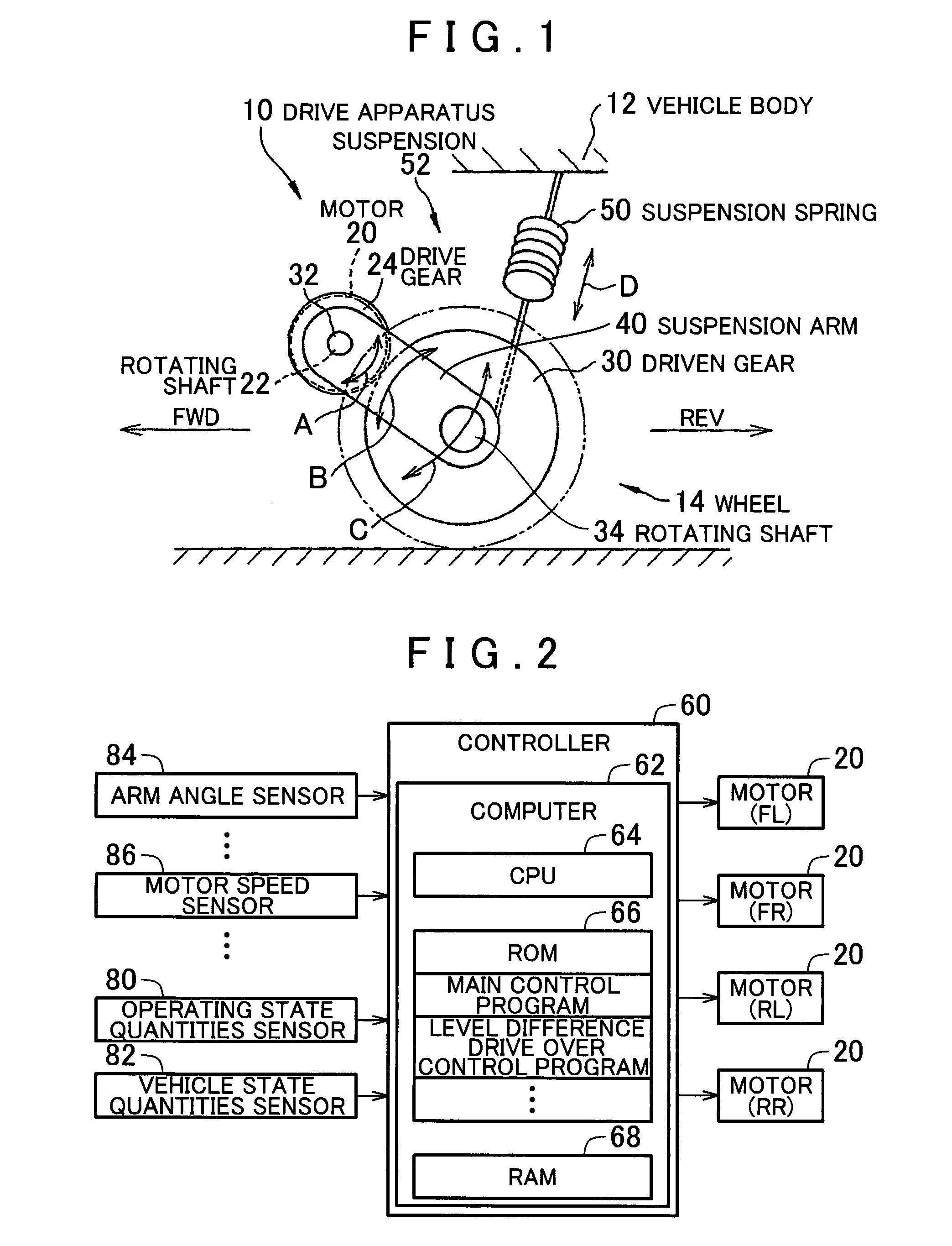
[0069] In FIG. 1, the mechanical structure of a wheel supporting and driving apparatus 10 is shown in a side view. However, the wheel 14 is shown as a phantom portion. This wheel supporting and driving apparatus 10 is mounted on a vehicle 14 that is provided with a vehicle body 12 and a plurality of wheels 14, which include left and right front wheels and left and right rear wheels. In FIG. 1, the wheel supporting and driving apparatus 10 is shown so as to focus on one of these wheels 14.

[0070] As shown in FIG. 1, each of the wheels of this wheel supporting and driving apparatus 10 is provided with a motor 20 that is fixed to the vehicle body 12 and a drive gear 24 that is linked coaxially with a rotating shaft 22 of this motor 20. The center of rotation of this drive gear 24 is decentered from the center of rotation of the wheel 14 in a direction that crosses the vertical direction. In the present embodiment, the motor 20 is supported by the vehicle body 12 such that substantially...

second embodiment

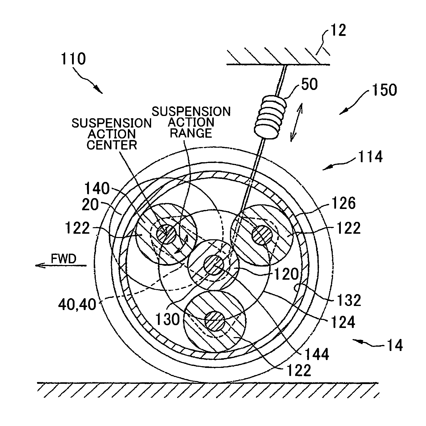
[0121] As shown in FIG. 9, the planetary gear mechanism 214, similar to the second embodiment, is structured so as to include a sun gear 220, a plurality of pinion gears 222, 222 and 222, a carrier 224, and the ring gear 226. The sun gear 220 rotates coaxially and integrally with the wheel 14. The ring gear 266 is linked to the hub 216 via a bearing or the like on the outer circumference thereof, and is rotated relative to the wheel 14. The sun gear 220 and the ring gear 226 rotate in opposite directions.

[0122] The plurality of pinion gears 222, 222, and 222 is disposed so as to be arranged on a circle that is coaxial with the sun gear 220, and they are disposed so as to mesh with outer teeth 230 of the sun gear 220 and mesh with inner teeth 232 of the ring gear 226. The plurality of pinion gears 222, 222, and 222 is retained by the carrier 224.

[0123] One of the plurality of pinion gears 222, 222, and 222 is selected to be an input pinion 240, and the motor 20 is coaxially linked t...


PUM


Abstract

A wheel supporting and driving device, comprising a motor (20) fixed to a vehicle body (12), a drive gear (24) coaxially rotated by the motor (20), and a driven gear (30) coaxially and integrally rotated with a wheel (14) which are installed in a vehicle. The drive gear (24) is rotated by the motor (20) around a rotating center decentered from the rotating center of the wheel (14) in a direction crossing perpendicularly to the vertical direction. Also, the device comprises a suspension arm (40) connecting the drive gear (24) to the driven gear (30) in the state of the driven gear (30) reciprocatingly swingable around the rotating center of the drive gear (24) and a suspension spring (50) elastically connecting the wheel (14) to the vehicle body (12).

Description

[0001] The disclosure of PCT International Publication No. WO 2006 / 062125 A1 filed on Dec. 7, 2005 including the specification, drawings and abstract is incorporated herein by reference in its entirety. BACKGROUND OF THE INVENTION [0002] 1. Field of the Invention [0003] The present invention relates to a technology in which wheels are supported in a vehicle so as to be able to move vertically with respect to the vehicle body, and each of the wheels is driven by a motor, and in particular, relates to a technology that simplifies a structure that realizes the ability to support the wheels and the ability to drive the wheels. [0004] 2. Description of the Related Art [0005] A vehicle in which wheels are supported so as to be able to move vertically with respect to a vehicle body and these wheels are driven by a motor is already known (refer, for example, to Japanese Patent Application Publication No. JP-A-H6-48192). [0006] In this type of vehicle, there is a demand to realize, for each ...

Claims


Application Information

Patent Timeline
Patent Type & Authority Applications(United States)
IPC IPC(8): B60K1/00
CPCB60G11/00B60G17/015B60G17/0157B60G17/0195B60G2204/30F16H1/227B60K7/0007B60K17/046B60K2007/0046B60K2007/0061B60L2220/46B60G2400/82B60L15/2054B60L2220/44B60L2240/421B60L2240/423B60L2270/145Y02T10/72Y02T10/64
Inventor TANIGUCHI, TAKAOMIKI, NOBUAKITACHIBANA, TAKUMI
Owner KABUSHIKIAISHA EQUOS RES
Why Eureka
Try Eureka