Mode selection amplifier circuit usable in a signal acquisition probe

a signal acquisition and amplifier circuit technology, applied in the field of amplifier circuits, can solve problems such as affecting the common mode measurement and inaccuracy of common mode measuremen

Inactive Publication Date: 2007-11-29
TEKTRONIX INC
View PDF9 Cites 18 Cited by
  • Summary
  • Abstract
  • Description
  • Claims
  • Application Information

AI Technical Summary

Benefits of technology

The patent describes a probe that can selectively measure different signals using a mode selection amplifier circuit. The probe has a control box that sends signals to the amplifier circuit to select the desired mode of measurement. The amplified signal is then sent to a differential output amplifier for further processing. The technical effect of this invention is that it allows for more accurate and selective measurement of signals in a probe.

Problems solved by technology

The technical problem addressed in this patent is the need for an amplifier circuit in a signal acquisition probe that can measure various types of electrical signals, including single ended and differential signals. The amplifier circuit should be able to generate different signal output modes, such as differential and common mode signals, and be usable in both single ended and differential signal acquisition probes. This will eliminate the need for a deskew fixture and algorithms and calibrate out any internal delays in the measurement instrument that may affect the common mode measurement.

Method used


Image

  • Mode selection amplifier circuit usable in a signal acquisition probe
  • Mode selection amplifier circuit usable in a signal acquisition probe
  • Mode selection amplifier circuit usable in a signal acquisition probe

Examples


Embodiment Construction

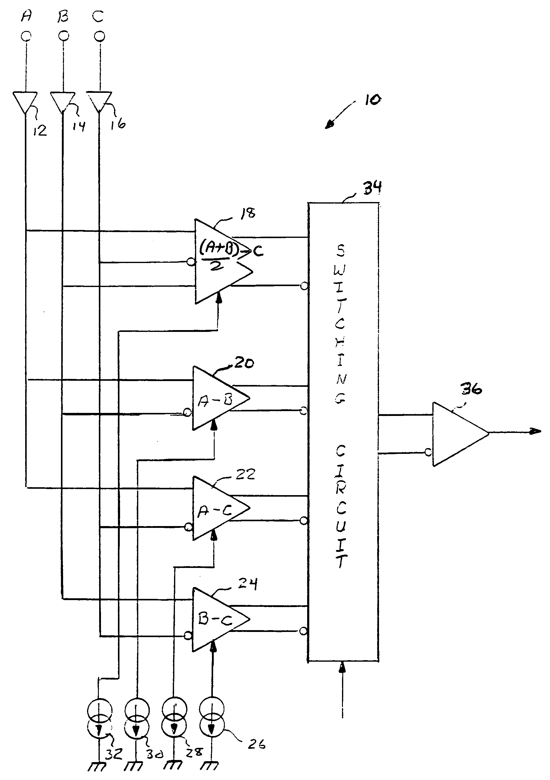
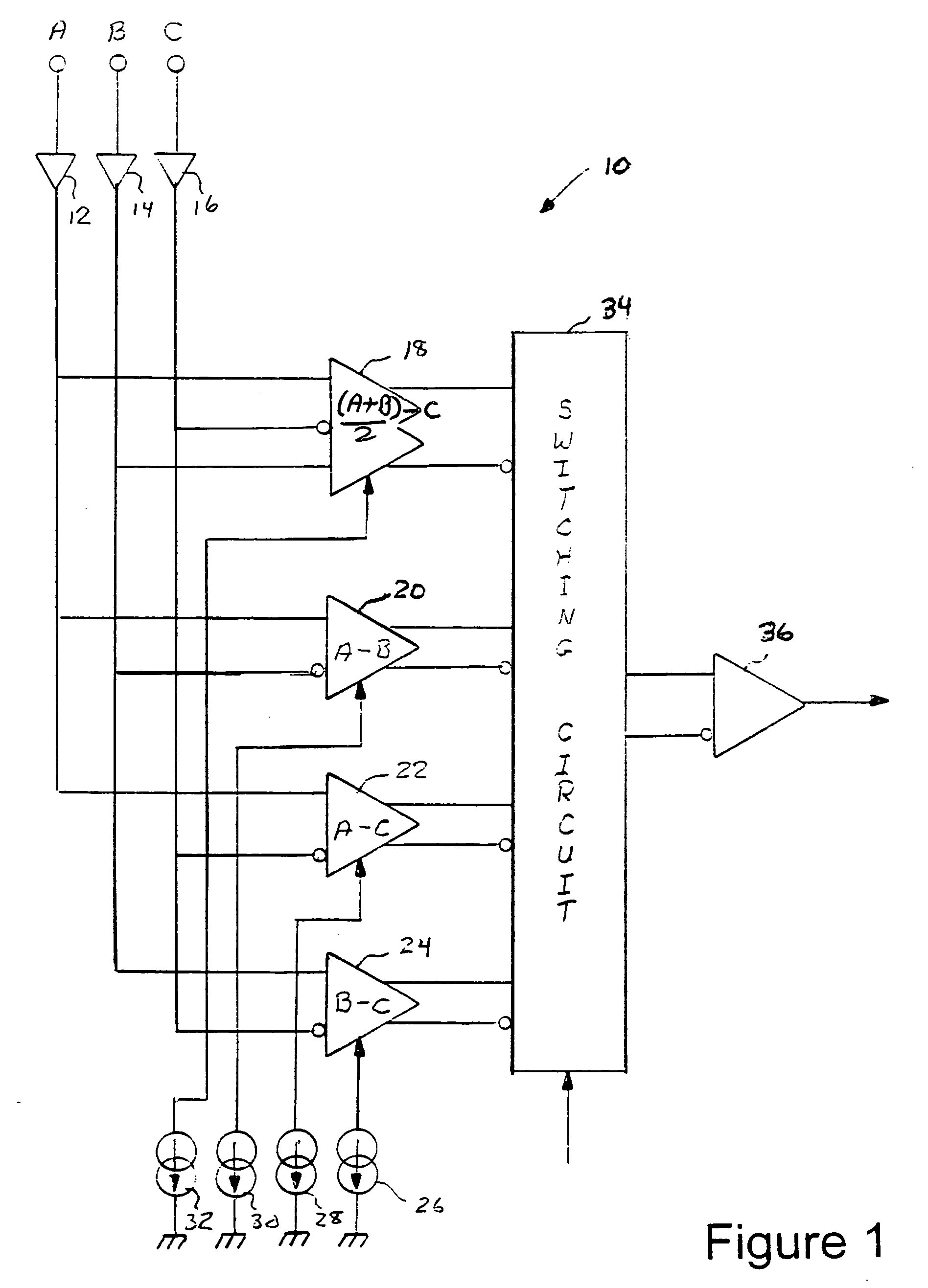
[0024]Referring to FIG. 1, there is shown a first embodiment of the mode selection amplifier circuit 10 for generating multiple signal output modes. The mode selection amplifier circuit 10 has inputs A, B, and C receiving voltage or current input signals A, B and C. The input signals may be single ended, represented by input signals A and C or input signals B and C, or differential, represented by input signals A and B, with the differential signal having common-mode components. The input signals A, B and C are coupled through buffer circuits 12, 14, and 16 to various inputs of differential amplifiers 18, 20, 22 and 24. Each differential amplifier 18, 20, 22 and 24 is coupled to a constant current source 26, 28, 30 and 32. Alternately, the differential amplifiers 18, 20, 22 and 24 may be coupled to a single current source having multiple current outputs. The differential outputs of each of the differential amplifiers 18, 2022 and 24 are coupled to a switching circuit 34. The switchi...


PUM


Abstract

A mode selection amplifier circuit has multiple differential amplifier circuits coupled to receive input signals A, B and C. Each differential amplifier circuit is selectively operable for generating a signal output representative of an output mode with the output mode of each differential amplifier circuit selected from one of algebraic combinations of the signal inputs A−C, B−C, A−B and (A+B)/2−C. The mode selection amplifier circuit is usable in a signal acquisition probe for providing various signal output modes to a measurement test instrument.

Description


Claims


Application Information

Patent Timeline
Owner TEKTRONIX INC
Why Eureka
Try Eureka