Cooling Apparatus, Cooled Electronic Module and Methods of Fabrication Thereof Employing A Thermally Conductive Return Manifold Structure Sealed To The Periphery Of A Surface To Be Cooled

a cooling apparatus and electronic module technology, applied in the direction of electrical apparatus construction details, direct contact heat exchangers, lighting and heating apparatuses, etc., can solve the problems of increased device temperature, thermal runaway conditions, increased power dissipation, and therefore heat production

Inactive Publication Date: 2007-11-29
IBM CORP
View PDF24 Cites 71 Cited by
  • Summary
  • Abstract
  • Description
  • Claims
  • Application Information

AI Technical Summary

Benefits of technology

[0009]The shortcomings of the prior art are overcome and additional advantages are provided through the provision of a cooling apparatus. The cooling apparatus includes a supply manifold structure including a plurality of inlet orifices for injecting coolant onto a surface to be cooled when the cooling apparatus is employed to cool at least one electronic device; and a return manifold structure having a surface configured to seal to the surface to be cooled when the cooling apparatus is employed to cool the at least one electronic device. The return manifold s

Problems solved by technology

This heat should be removed from the devices in order to maintain device junction temperatures within desirable limits, with failure to remove the heat thus produced resulting in increased device temperatures, potentially leading to thermal runaway conditions.
First, power dissipation, and therefore heat production, increases as device operating frequencies increase.
Further, as more and more devices are packed onto a single chip, power density (Watts/cm

Method used


Image

  • Cooling Apparatus, Cooled Electronic Module and Methods of Fabrication Thereof Employing A Thermally Conductive Return Manifold Structure Sealed To The Periphery Of A Surface To Be Cooled
  • Cooling Apparatus, Cooled Electronic Module and Methods of Fabrication Thereof Employing A Thermally Conductive Return Manifold Structure Sealed To The Periphery Of A Surface To Be Cooled
  • Cooling Apparatus, Cooled Electronic Module and Methods of Fabrication Thereof Employing A Thermally Conductive Return Manifold Structure Sealed To The Periphery Of A Surface To Be Cooled

Examples


Embodiment Construction

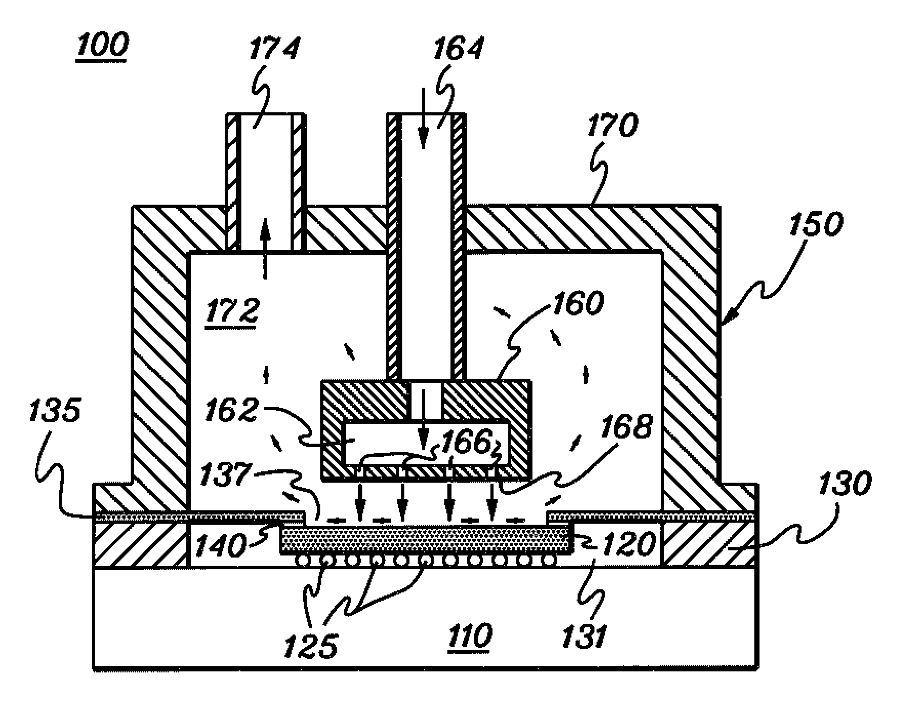
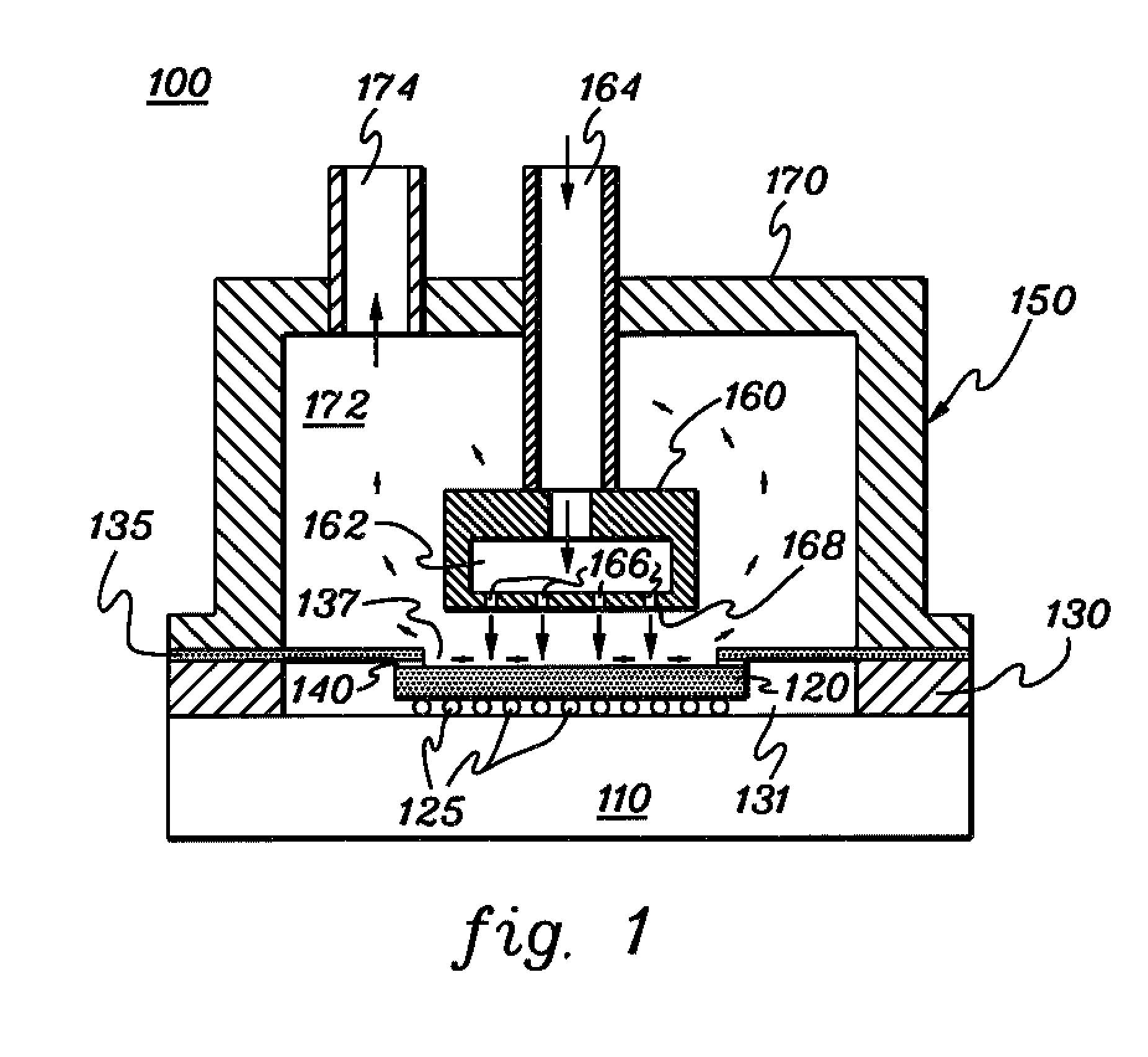
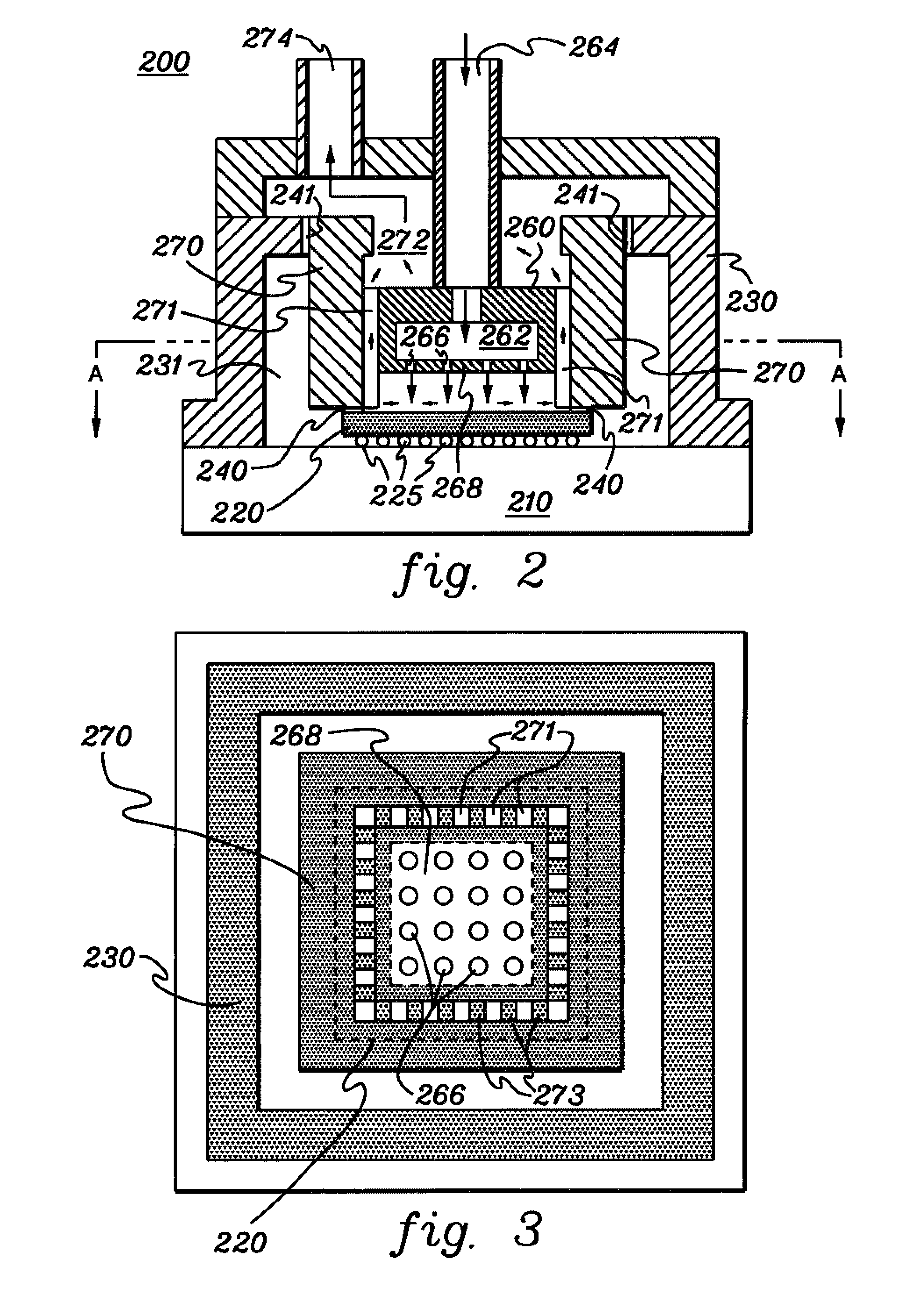
[0019]As used herein “electronic device” comprises any heat generating electronic component of a computer system or other electronic system requiring cooling. In one example, the electronic device is or includes an integrated circuit chip, a semiconductor chip and / or an electronic component. The term “cooled electronic module” includes any electronic module with cooling and at least one electronic device, with single-chip modules and multi-chip modules being examples of a cooled electronic module as described herein. The “surface to be cooled” refers to a surface of the electronic device itself or to an exposed surface of a thermal cap, thermal spreader, passivation layer, or other surface in contact with the electronic device, and through which heat generated by the electronic device is to be extracted. As used herein, “micro-scaled” means a characteristic dimension of 250 micrometers (microns) or less.

[0020]Generally stated, provided herein are enhanced cooling apparatuses and met...


PUM


Abstract

A cooled electronic module and method of fabrication are provided employing a cooling apparatus for removing heat from one or more electronic devices disposed on a substrate. The cooling apparatus includes a supply manifold structure having a plurality of inlet orifices for injecting coolant onto a surface to be cooled, and a return manifold structure. The return manifold structure, which is fabricated of a thermally conductive material, has a base surface sealed to the surface to be cooled along a periphery thereof employing a thermally conductive, coolant-tight seal. The return manifold structure provides at least one return passageway for exhausting coolant after impinging on the surface to be cooled, wherein coolant exhausting through the at least one passageway cools the return manifold structure, thereby facilitating further cooling of the surface to be cooled in a region where the base surface is sealed to the surface to be cooled.

Description

CROSS REFERENCE TO RELATED APPLICATIONS[0001]This application contains subject matter which is related to the subject matter of the following applications, each of which is assigned to the same assignee as this application and each of which is hereby incorporated herein by reference in its entirety:[0002]“Electronic Device Substrate Assembly With Multilayer Impermeable Barrier and Method of Making”, Chu et al., U.S. Pat. No. 6,940,712, issued Sep. 6, 2005;[0003]“Fluidic Cooling Systems and Methods for Electronic Components,” Pompeo et al., Ser. No. 10 / 904,555; filed Nov. 16, 2004;[0004]“Cooling Apparatus, Cooled Electronic Module and Methods of Fabrication Thereof Employing an Integrated Coolant Inlet and Outlet Manifold,” Campbell et al., Ser. No. 11 / 124,513, filed May 6, 2005; and[0005]“Cooling Apparatus, Cooled Electronic Module and Methods of Fabrication Thereof Employing An Integrated Manifold And A Plurality of Thermally Conductive Fins,” Campbell et al., Ser. No. 11 / 124,064, ...

Claims


Application Information

Patent Timeline
IPC IPC(8): F28F7/00H05K7/20
CPCF28C3/08F28F7/00Y10S165/908H01L2224/73253H01L23/4735H05K7/20772
Inventor CAMPBELL, LEVI A.CHU, RICHARD C.ELLSWORTH, MICHAEL J.IYENGAR, MADHUSUDAN K.SCHMIDT, ROGER R.SIMONS, ROBERT E.
Owner IBM CORP
Why Eureka
Try Eureka