Swept kickers for vertical mixer augers

a vertical mixer and auger technology, applied in the field of vertical mixers, can solve the problems of reducing discharge efficiency, clogging or restricting the discharge area, and conventional augers and kickers have had little success in solving this particular clogging problem, so as to improve the interaction of feed materials, eliminate clogging of lighter materials, and accelerate discharge speed

Active Publication Date: 2007-11-29
KUHN NORTH AMERICA
View PDF9 Cites 33 Cited by
  • Summary
  • Abstract
  • Description
  • Claims
  • Application Information

AI Technical Summary

Benefits of technology

[0013] to provide a mixer which has improved interaction of the feed materials between the container and the discharge opening;
[0014] to provide a mixer in which feed materials are discharged in a more even manner, providing a smooth flow through the discharge opening when the discharge door is opened;
[0016] to provide a mixer in which the kickers help to eliminate clogging of lighter weight feed materials being discharged through the discharge opening.
[0017] In accordance with the present invention, a vertical type mixer comprises an auger with swept kickers, to help discharge feed materials smoothly and quickly.

Problems solved by technology

Therefore, discharge efficiency is reduced.
Especially in the case of relatively lightweight materials, the discharge area can become clogged or restricted.
Conventional augers and kickers have had little success in resolving this particular clogging problem, as the kickers are typically designed with a straight edge radiating from the auger core to facilitate a rotary action, as opposed to an outward action toward the door opening.
Thus, one disadvantage of straight auger kickers is that lightweight materials can clog during attempted discharge from the discharge opening.
Another disadvantage of having straight kickers is that feed materials are urged towards the discharge opening only during the first half of the rotation past the discharge opening, after which materials are pulled back inward.
Yet another disadvantage of having straight kickers is that the feed materials tend to pulse as they are discharged through the discharge opening, rather than discharge with a more desirable steady flow.

Method used


Image

  • Swept kickers for vertical mixer augers
  • Swept kickers for vertical mixer augers
  • Swept kickers for vertical mixer augers

Examples


Embodiment Construction

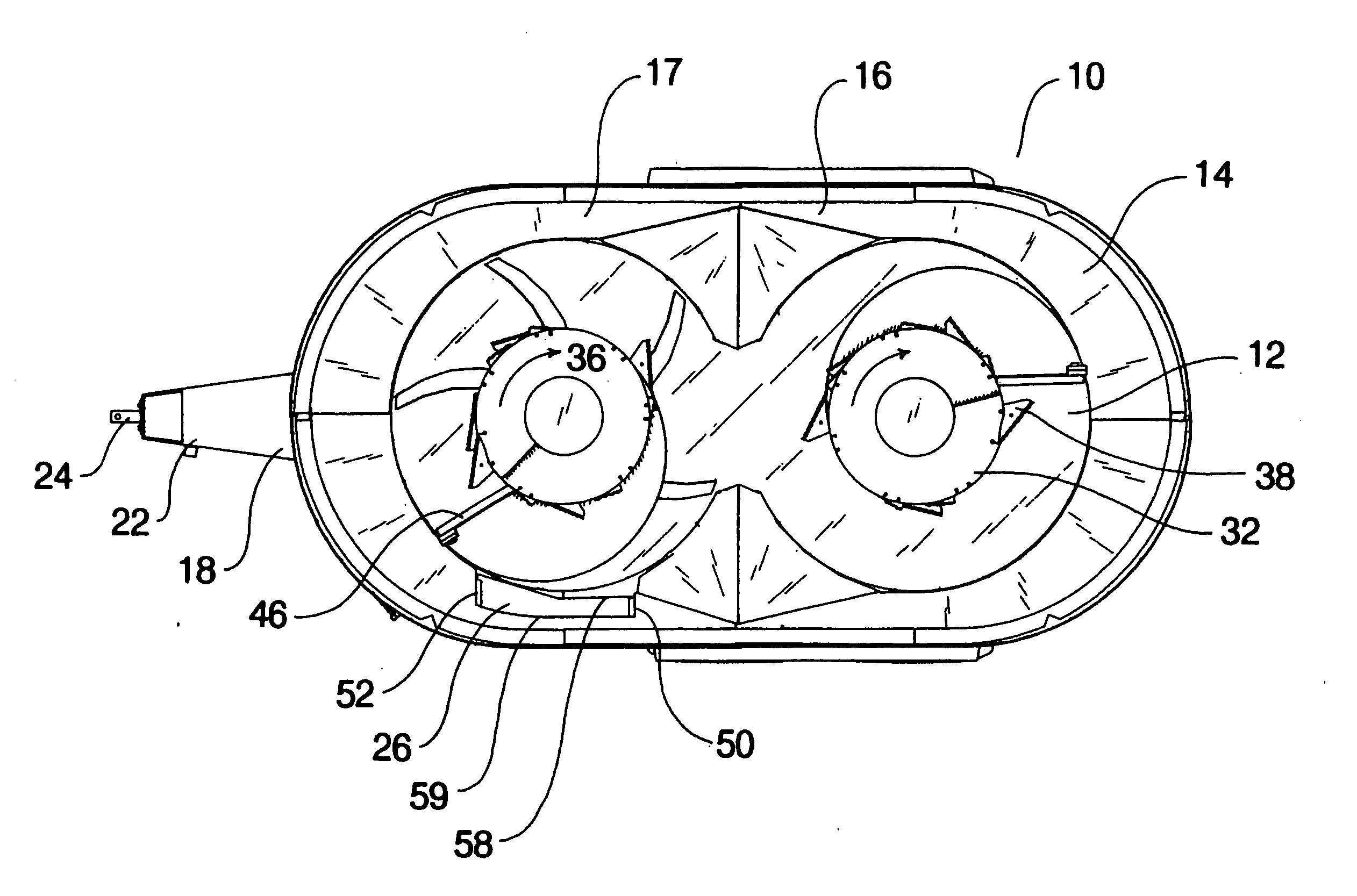
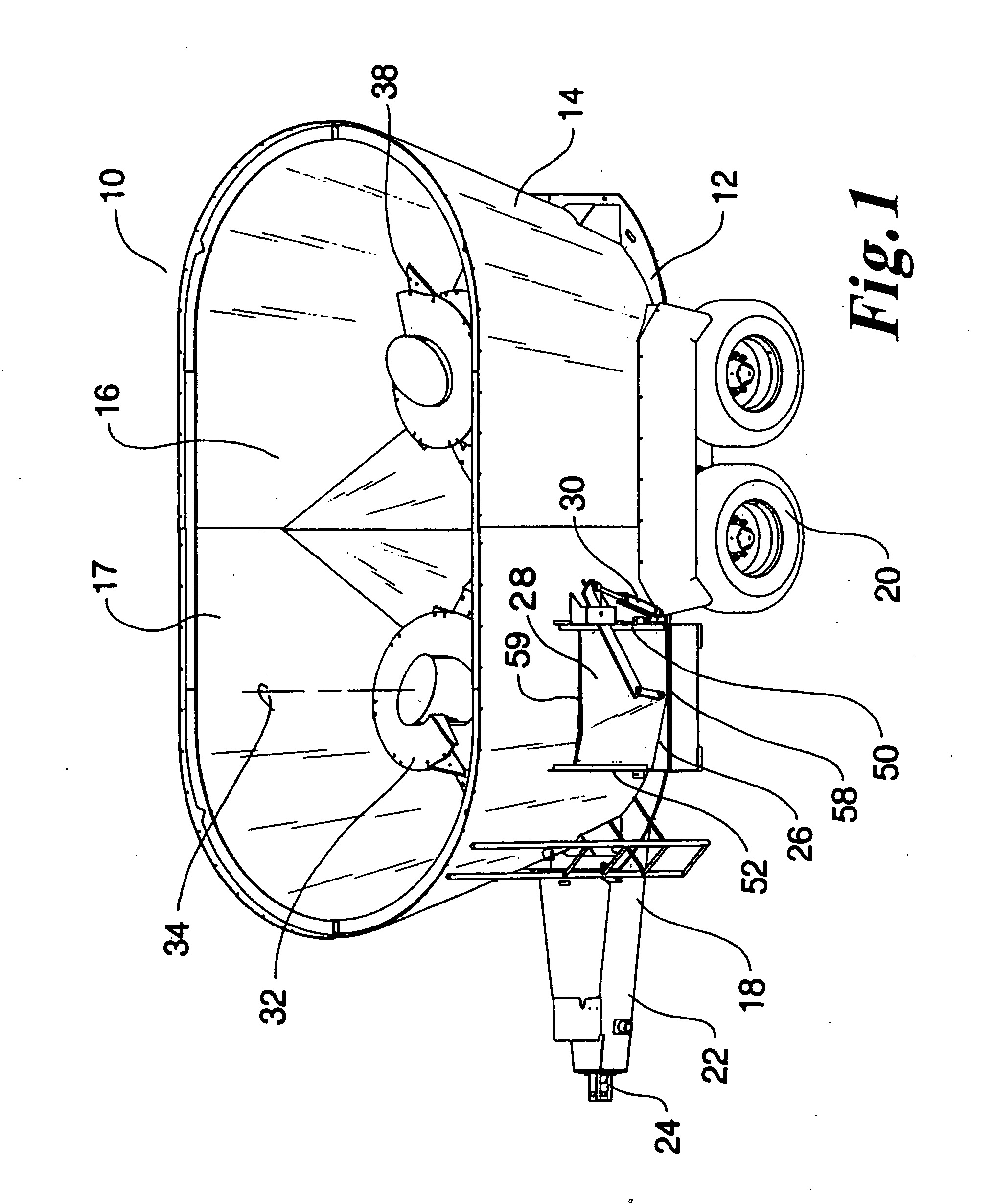
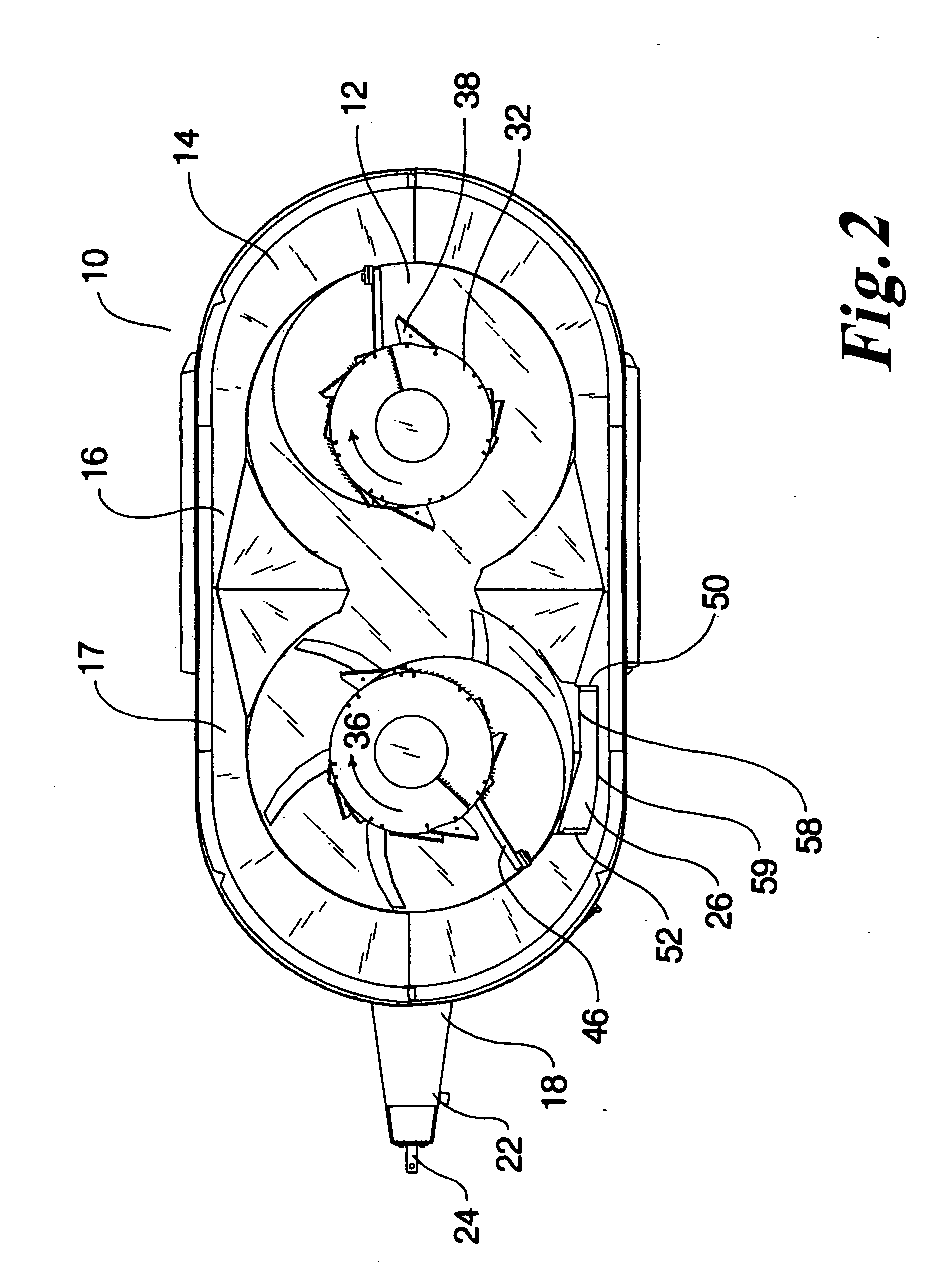
[0025] With reference to the FIGS. 1 and 2, a vertical feed mixer is generally designated by the reference number 10. The mixer includes a floor 12 and a wall 14 attached to the floor. The combination of the floor 12 and wall 14 defines a container 16 with a top opening 17. The mixer is mounted upon a frame 18 including wheels 20. A tongue 22 extending from the frame 18 is adapted to be hitched to a tractor or other prime mover via a hitch 24 so that the mixer may be pulled in a direction of travel. In other words, the wheels 20 beneath the frame 18 allow the mixer to be pulled in a line behind a vehicle so that feed may be mixed and discharged over a larger area. The wall 14 includes a discharge opening 26 adjacent to the floor 12, with a discharge door 28 movable between open and closed positions by a hydraulic cylinder 30. An auger 32 is rotatably mounted within the container 16 and rotates around an axis of rotation 34 in a direction of rotation 36. The auger 32 can include shar...


PUM


Abstract

A vertical feed mixer apparatus has a container for the reception of feed. The container includes a floor, a wall extending away from the floor such that the wall is disposed above the floor. The wall has a top opening disposed remotely from the floor to define an enclosure for feed received through the top opening. The container has a discharge opening in the wall adjacent to the floor. There is at least one auger disposed within the enclosure. The auger includes an auger core with an axis of rotation extending substantially vertically through the floor. The auger has a helical flighting secured to and disposed around the auger core. The auger has at least one swept kicker secured to the auger core or flighting, disposed adjacent to the floor, and configured to discharge the feed through the discharge opening.

Description

CROSS-REFERENCE TO RELATED APPLICATIONS [0001] Not Applicable BACKGROUND OF THE INVENTION [0002] 1. Field of the Invention [0003] This invention relates to augers for agricultural mixers, specifically vertical type feed mixers. [0004] 2. Discussion of Background Art [0005] Agricultural mixers are used for mixing hay and silage together with other nutrients including animal feed supplements and grains. These feed materials are then discharged and fed to various livestock such as cattle and dairy cows. Sometimes the mixing of such feed includes depositing a whole round or square bale of hay into the mixer. The mixer then cuts and processes the bale into the desired consistency before and during the mixing of the other feed nutrients. [0006] In conventional mixers, there are many different configurations including horizontal augers, reel type arrangements, and vertical augers. In the vertical auger type mixers, the auger designs are generally similar from mixer to mixer. The auger for ...

Claims


Application Information

Patent Timeline
Patent Type & Authority Applications(United States)
IPC IPC(8): B01F7/24
CPCA01K5/004B01F7/241B01F15/0267B01F15/00792B01F7/245Y10S366/603B01F27/922B01F27/9212B01F35/452B01F35/751
Inventor ALBRIGHT, CHRIS
Owner KUHN NORTH AMERICA
Why Eureka
Try Eureka