
Method for Monitoring the Synchronism of Transmitters in a Common Wave Network

synchronization technology, applied in the field of synchronization monitoring of transmitters in a common wave network, can solve the problems of unsatisfactory requirements of synchronization and adequate signal level, and achieve reliable and unequivocal error source identification with respect, the comparison of the transit time of two transmitters, and the effect of synchronization

Inactive Publication Date: 2007-11-29
ROHDE & SCHWARZ GMBH & CO KG
View PDF4 Cites 2 Cited by
  • Summary
  • Abstract
  • Description
  • Claims
  • Application Information

AI Technical Summary

Benefits of technology

[0010] A need therefore exists to develop a method for monitoring the synchronism of transmitters in a common wave network such that, on the one hand, unequivocal monitoring of the absolute synchronism of all the transmitters integrated in one common wave network is possible and, on the other hand, conclusions can be drawn from the measurement of an occurring asynchronism as unequivocally and easily as possible with respect to the error source or at least to the type of error source of the occurring asynchronism.

Problems solved by technology

Because of the most varied of interferences—e.g. too little transmission power of a transmitter, defective synchronisation of a transmitter to the common wave network, different weather conditions in the transmission region of the common wave network etc.—the requirements of synchronism and adequate signal level can be unfulfilled for an interference-free reception in the common wave network.
The disadvantage of this method is the merely paired comparison of the transit times of two transmitters with respect to the synchronism of two transmitters relative to each other.
Reliable and unequivocal error source identification with respect to error sources which have an effect on only one single transmitter (e.g. phase detuning of a single transmitter) and error sources which have an effect on a transmitter group (e.g. transmission errors in the supply route to the transmitter group) cannot be achieved with this method.
Because of the merely paired comparison of the transit time differences of two receiving signals, the method has the further disadvantage that only relative asynchronism between two transmitters to be surveyed can be identified, whereas the absolute asynchronism of the respective transmitters relative to a reference transmitter and hence to the entire common wave network is not possible.

Method used


Image

  • Method for Monitoring the Synchronism of Transmitters in a Common Wave Network
  • Method for Monitoring the Synchronism of Transmitters in a Common Wave Network
  • Method for Monitoring the Synchronism of Transmitters in a Common Wave Network

Examples


Embodiment Construction

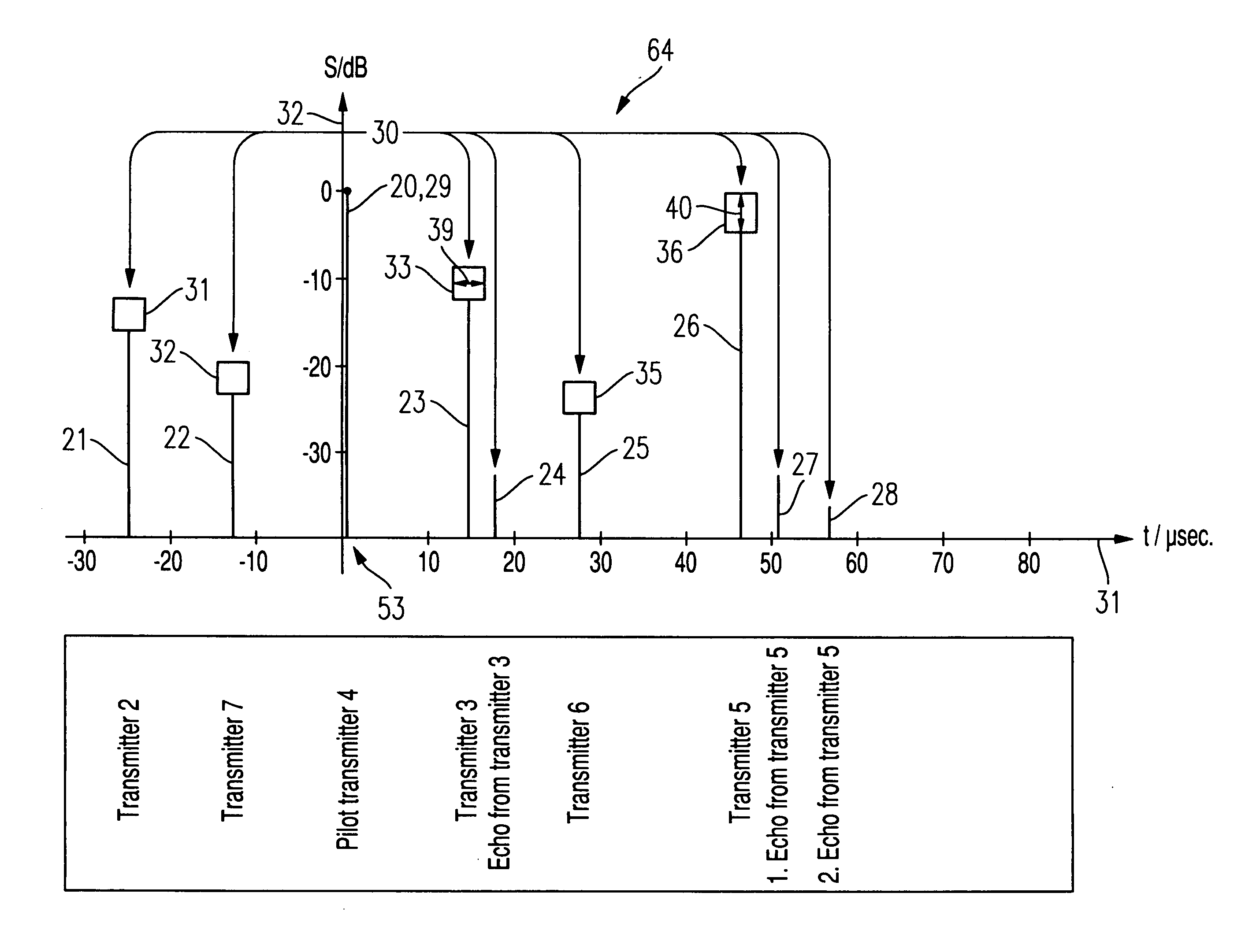
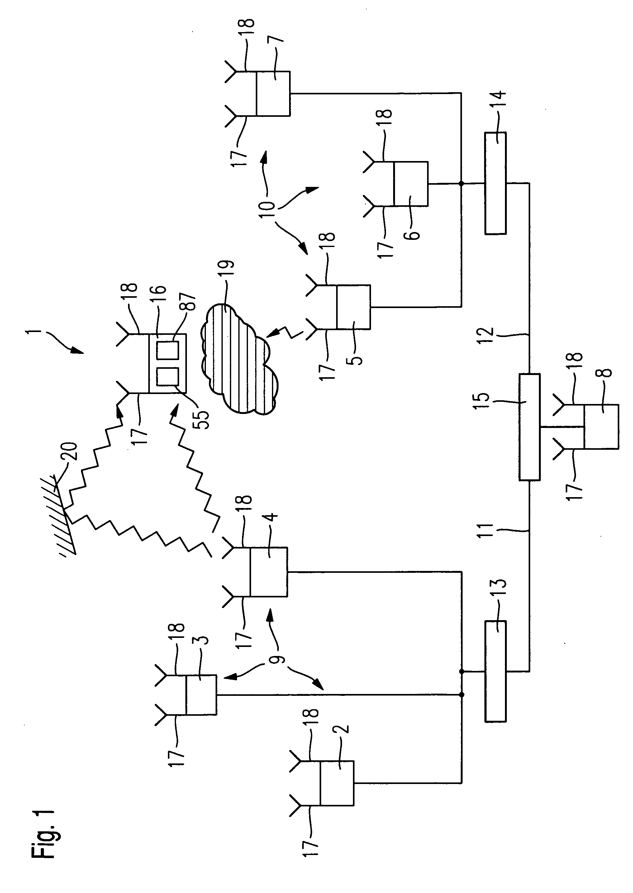
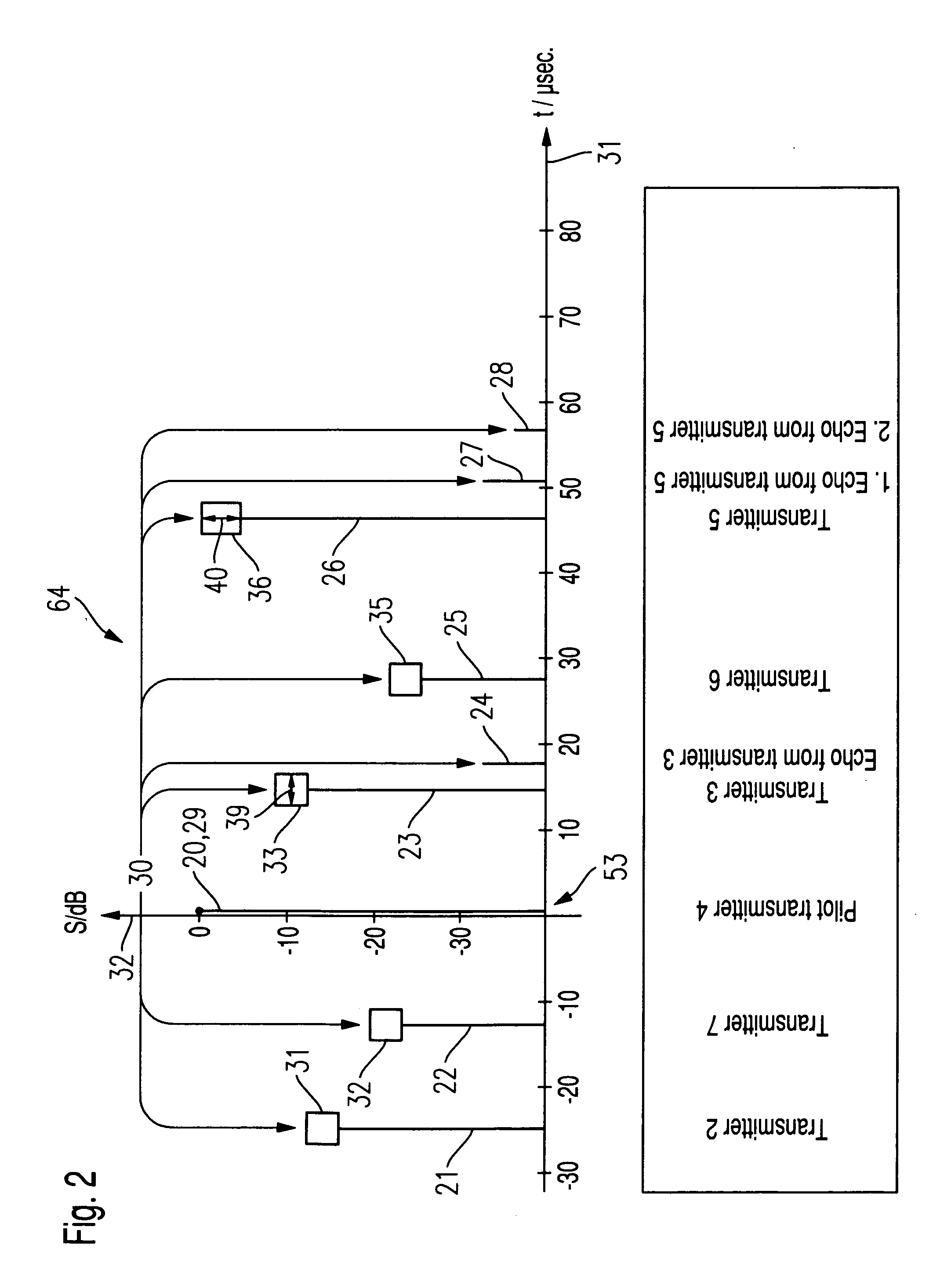
[0026] The method according to the invention for monitoring the synchronism of transmitters in a common wave network is described subsequently in an embodiment with reference to FIG. 1 to 6B.

[0027] According to FIG. 1, a common wave network 1 comprises for example the transmitters 2, 3, 4, 5, 6 and 7, which are distributed in the transmitter region and a central office 8. In this exemplary common wave network 1, the transmitters 2, 3 and 4 are combined into a first transmitter group 9 and the transmitters 5, 6 and 7 into a second transmitter group 10. The first transmitter group 9 is connected to the central office 8 via a first common supply route 11, whilst the second transmitter group 10 is connected likewise to the central office 8 via the second common supply route 12. The coupling of the transmitters 2, 3 and 4 to the first supply route 11 is effected via a first distribution device 13, whilst the coupling of the transmitters 5, 6 and 7 to the second supply route 12 is effect...


PUM


Abstract

A method for monitoring the time synchronization of a total of n transmitters in a common wave network is described in which a reference total pulse response is compared with a measured total pulse response belonging to the transmission channels of the n transmitters of the common wave network. A reference pulse response is fixed in the reference total pulse response in relation to the pilot pulse response, on the basis of which the remaining reference pulse responses are references to classify synchronization errors in the common wave network in various synchronization error categories.

Description

BACKGROUND OF THE INVENTION [0001] The invention relates to a method for monitoring the synchronism of transmitters in a common wave network. [0002] Transmission technology of terrestrial radio and television is based on a network of regionally distributed transmitters which transmit synchronously at the same transmitter frequencies (common wave network). The technology of common wave networks could only be achieved with the introduction of digital transmission methods in which, according to the transmission standard, protective intervals (guard intervals) are provided which make it possible to have a specific tolerance range for different transit times of the transmission signals from the individual transmitters because of different distances. Modern digital multicarrier methods (e.g. OFDM=orthogonal frequency division multiplexing) of digital radio (DAB=digital audio broadcasting) and of digital terrestrial television (DVB-T=digital video broadcasting terrestrial) are therefore ba...

Claims


Application Information

Patent Timeline
IPC IPC(8): H04L7/00H04H20/67H04N5/04H04N5/44H04N17/00
CPCH04B7/2625H04H20/67H04N5/04H04N21/6112H04N17/004H04N21/4302H04N21/44209H04N5/4401H04N21/426
Inventor BALZ, CHRISTOPHHOFMEISTER, MARTIN
Owner ROHDE & SCHWARZ GMBH & CO KG
Learn More