Implantable Bone-Vibrating Hearing Aid

Inactive Publication Date: 2007-11-29
CHUNG YUAN CHRISTIAN UNIVERSITY
View PDF4 Cites 20 Cited by
  • Summary
  • Abstract
  • Description
  • Claims
  • Application Information

AI Technical Summary

Benefits of technology

[0008]The present invention proposes an implantable bone-vibrating hearing aid, including a magnetic transmitting module for receiving an audio-converted signal and generating a driving force, the magnetic transmitting module including a transmitting coil for receiving the audio-converted signal and generating a corresponding magnetic field and a magnetic conducting element for sensing the corresponding magnetic filed to generate the driving force, a vibrating module for receiving the driving force and generating a vibration and an acoustic impedance element for receiving knockings of the vibration generated by the vibrating module, wherein the magnetic conducting element, the vibrating module and the acoustic impedance element are implanted beneath a skin of a user, and the acoustic impedance element is in close contact with the temporal bone of the ear of the user, thereby enhancing the transmission of knocking energy of the vibrating module.
[0009]The present invention proposes an implantable bone-vibrating hearing aid, including a microphone for receiving an audio signal and outputting a converted signal, a power amplifier for receiving and amplifying the converted signal to output an audio-converted signal, a transmitting coil for receiving the audio-converted signal and generating a corresponding magnetic field, a magnetic conducting element for sensing the corresponding magnetic filed to generate the driving force, a vibrating module for receiving the driving force and generating a vibration, and an acoustic impedance element for receiving knockings of the vibration generated by the vibrating module, wherein the magnetic conducting element, the vibrating module and the acoustic impedance element are implanted beneath a skin of a user, and the acoustic impedance element is in close contact with the temporal bone of the ear of the user, thereby enhancing the transmission of knocking energy of the vibrating module.

Problems solved by technology

However, the wound created will always exist and wound infection can be a potential problem.
Also, such hearing aid is very expensive.

Method used


Image

  • Implantable Bone-Vibrating Hearing Aid
  • Implantable Bone-Vibrating Hearing Aid
  • Implantable Bone-Vibrating Hearing Aid

Examples


Embodiment Construction

[0015]The present invention will be described in the following with certain embodiments thereof. However, in addition to the disclosed embodiments, the present invention can be widely implemented in other embodiments. The scope of the present invention is not limited to the embodiments set forth, but are construed to be defined in the appended claims. In order to provide a more lucid description and a better understanding of the present invention to those with ordinary skill in the art, some portions of the diagrams are not drawn to scale, while some may be exaggerated and / or irrelevant parts omitted for clarity.

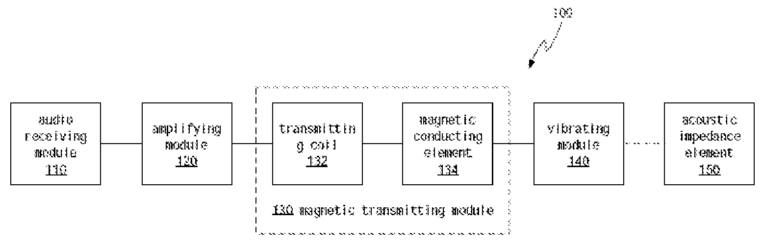
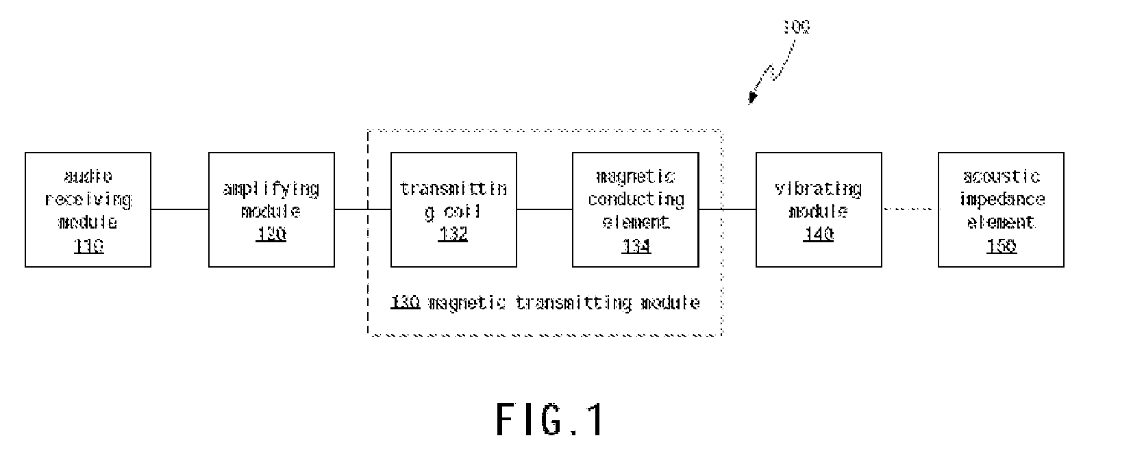
[0016]Referring to FIG. 1, a system block diagram of a preferred embodiment 100 of the present invention is shown. An audio receiving module 110 receives audio signal and outputs a converted signal, in this embodiment, the audio receiving module 110 may be a microphone or a sound source generator. An amplifying module 120 receives and amplifies the converted signal outputted...


PUM


Abstract

The present invention proposes an implantable bone-vibrating hearing aid, including a transmitting coil for receiving an audio-converted signal and generating a corresponding magnetic field, a magnetic conducting element for sensing the corresponding magnetic filed to generate a driving force, and a vibrating module for receiving the driving force and generating a vibration, wherein the magnetic conducting element and the vibrating module are implanted beneath a skin of a user, and the vibration generated by the vibrating module knocks on the temporal bone of the ear of the user, which generates mechanical waves that propagate to the inner ear of the user, creating a sense of hearing thereto.

Description

BACKGROUND OF THE INVENTION[0001]1. Field of the Invention[0002]The present invention generally relates to hearing aids, and more particularly to an implantable bone-vibrating hearing aid.[0003]2. Description of the Prior Art[0004]Conventional Bone-Anchored Hearing Aid (BAHA) involves implanting a vibrating device made of titanium metal into the temporal bone of the ear of a user by surgery. However, the wound created will always exist and wound infection can be a potential problem. Also, such hearing aid is very expensive. In addition, a Japanese scholar named Shinji Hamanishi has invented a non-invasive electromagnetic-stimulated hearing aid (Shinji Hamanishi, Takuji Koike, Hidetoshi Matsuki, and Hiroshi Wada. “A New Electromagnetic Hearing Aid Using Lightweight Coils to Vibrate the Ossicles”, IEEE Trans. on Magnetics, vol. 40, No. 5, September 2004), in which the system structure includes a core, a driving and induction coil, a special magnet and vibrator coil. Within this system...

Claims


Application Information

Patent Timeline
IPC IPC(8): H04R25/00
CPCH04R25/606
Inventor TSAI, CHENG-LUNCHEN, MIN-CHIHPAN, SHIH-WEI
Owner CHUNG YUAN CHRISTIAN UNIVERSITY
Why Eureka
Try Eureka