

Exercise Therapy Device
a technology of exercise therapy and device, which is applied in the field of exercise therapy devices, can solve the problems of affecting the sudden load of the exerciser the considerable load of the pedal at the start of the exercise therapy, so as to maintain the physical strength of the exerciser, and reduce the intensity of exercise.
- Summary
- Abstract
- Description
- Claims
- Application Information
AI Technical Summary
Benefits of technology
Problems solved by technology
Method used
Image

Examples
embodiment 1
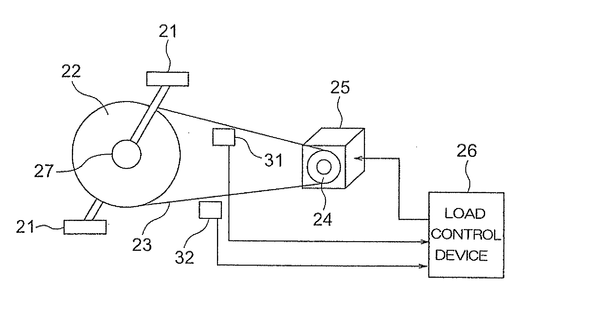
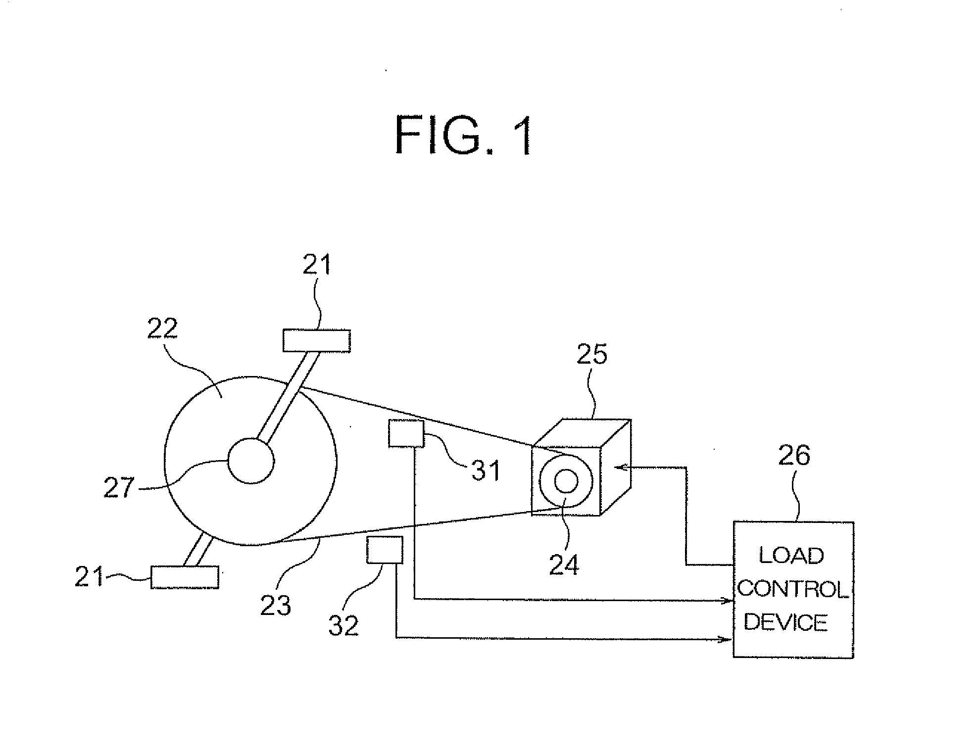
[0014]FIG. 1 is a block diagram showing the overall construction of an exercise therapy device according to Embodiment 1 of the present invention. As shown in FIG. 1, in the exercise therapy device of this embodiment, there is provided a pedal shaft pulley 22 connected with a rotation shaft 27 of pedals 21. Further, there is provided a load motor 25 for effecting a rotating motion of the pedal rotation shaft 27 of the pedals 21. Further, a load side pulley 24 is connected with the load motor 25. A belt 23 is looped around the pedal shaft pulley 22 and the load side pulley 24. The belt 23 constitutes a drive transmission means for transmitting the rotating motion of the pedal rotation shaft 27 to the load motor 25. Further, connected to the load motor 25 is a load control device 26 for drive-controlling the load motor 25. With this construction, the pedal shaft pulley 22 transmits a rotating motion through the belt 23 to the load motor 25 connected with the load side pulley 24, and t...
PUM
 Abstract
Description
Claims
Application Information