Cervical intervertebral prosthesis

a cervical vertebral and prosthesis technology, applied in the field of cervical vertebral prosthesis, can solve problems such as affecting the stability of fixation

Inactive Publication Date: 2007-11-29
CERVITECH INC
View PDF5 Cites 8 Cited by
  • Summary
  • Abstract
  • Description
  • Claims
  • Application Information

AI Technical Summary

Benefits of technology

[0003] This shortcoming is remedied by the features of the invention as set forth in this application. According to this, an instrument for positioning a fastening device at a vertebral body in order to secure an intervertebral prosthesis is provided that is separate from the fastening device and comprises two cover plates configured to be connected to adjacent vertebral bodies and a prosthesis core which forms an articular joint with one of the cover plates, the instrument comprising a drill gauge for the fastening device which is configured to be connected to the prosthesis or a prosthesis model in a predetermined relative position, wherein the drill gauge is slanted to point at an oblique angle towards the cover plates. In this way, the slanted drill gauge facilitates creation of a fixation hole that intersects with the cover plate, thus allowing insertion of a fixation device, like a screw or a nail, into the fixation hole interlocking with the cover plate. Hence, the prosthesis is securely held in place.

Problems solved by technology

This prevents the securing plates or the bracket from bearing across their entire surface on the vertebral bodies, and it impairs the stability of the fixation.

Method used


Image

  • Cervical intervertebral prosthesis
  • Cervical intervertebral prosthesis
  • Cervical intervertebral prosthesis

Examples


Embodiment Construction

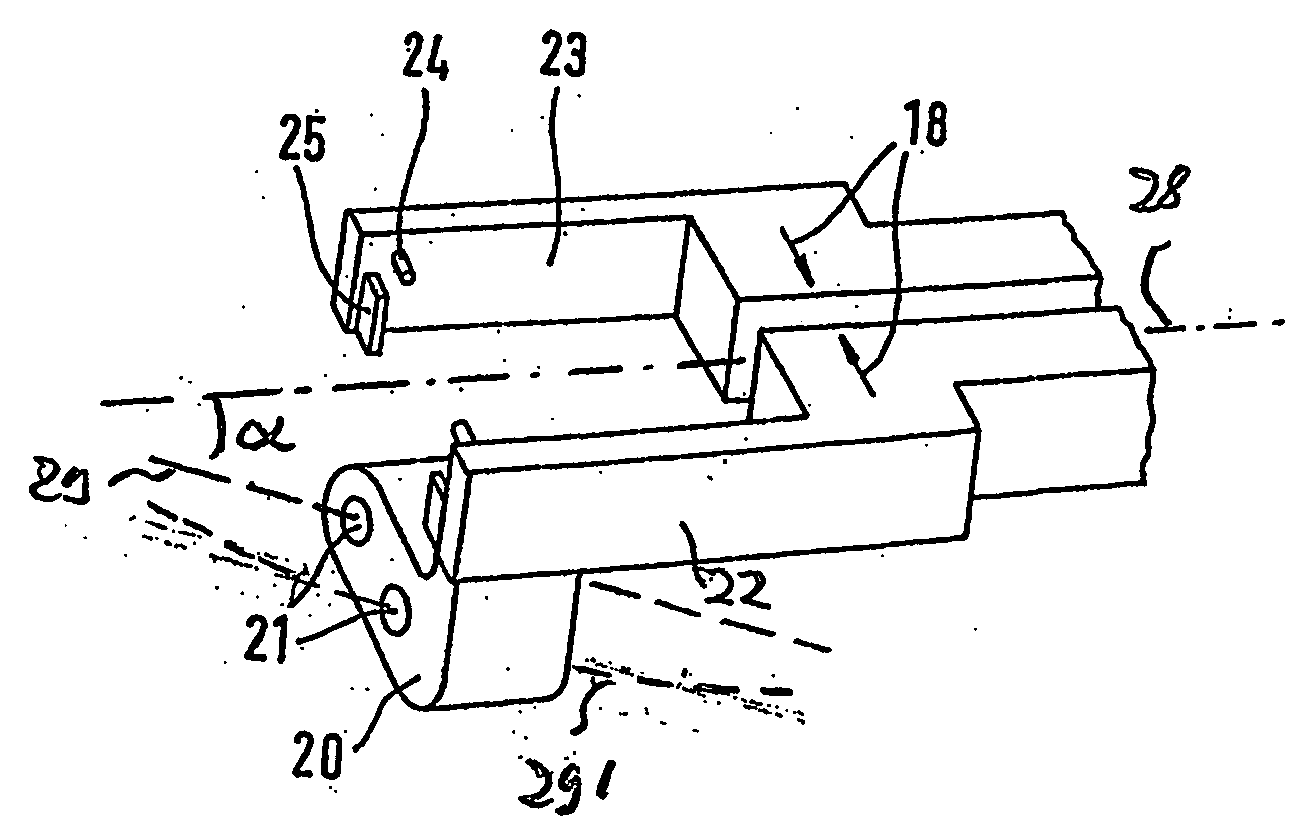
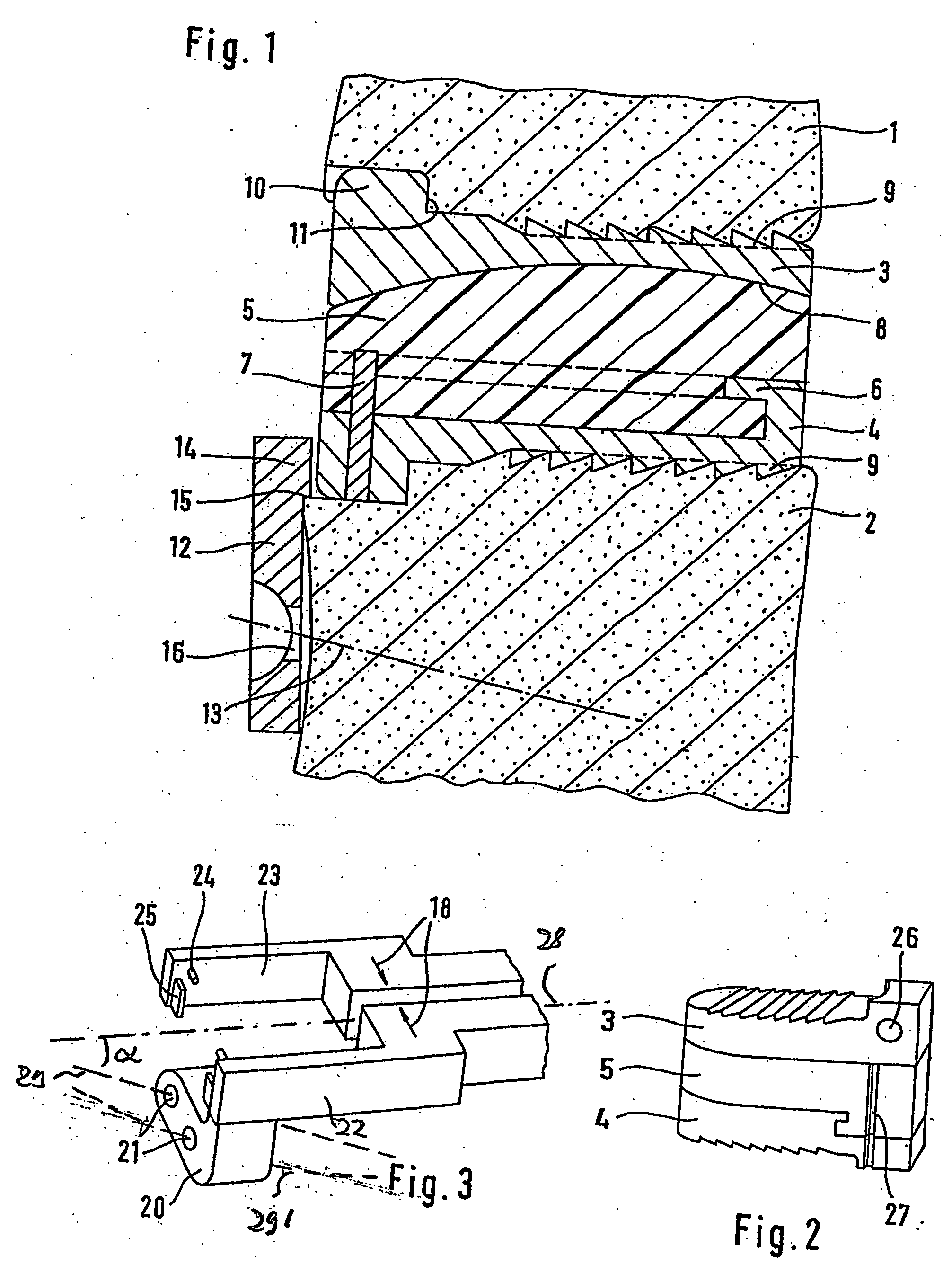
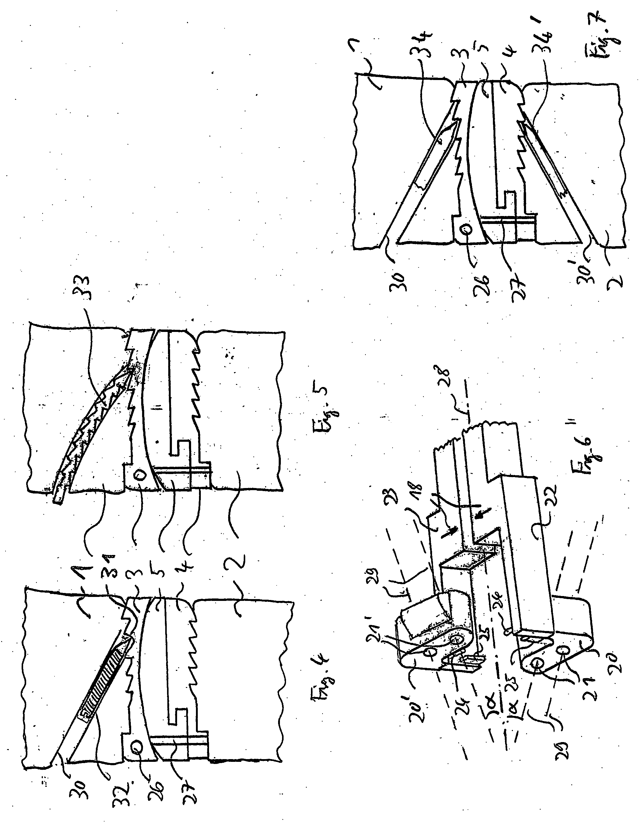
[0015] Between the vertebrae 1 and 2 of the cervical spine there is an intervertebral space into which is inserted the intervertebral prosthesis consisting of an upper cover plate 3, a lower cover plate 4, and a prosthesis core 5. The prosthesis core 5 is held on the lower cover plate 4 by profiles 6 and a catch 7. With the upper cover plate 3, it forms a slide surface pairing 8. The cover plates 3 and 4 have a sawtooth formation 9 by means of which they are held on the associated end plates of the vertebral bodies 1, 2. Short flanges 10 with dorsally facing limit stop surfaces 11 ensure that the cover plates 3, 4 cannot move farther than is wanted in the dorsal direction relative to the vertebral bodies 1, 2. An undesired movement in the ventral direction is generally prevented by the sawtooth formation of the profiles 9. This at least applies several months after the operation, when the bone tissue has grown into the surface of the cover plates and has connected firmly to them. De...


PUM

PropertyMeasurementUnit
heightaaaaaaaaaa
angleaaaaaaaaaa
angleaaaaaaaaaa

Abstract

A cervical intervertebral prosthesis includes at least one cover plate that is configured to be connected to one of two adjacent vertebral bodies and an instrument for positioning a fastening device at one of the vertebral bodies in order to secure the intervertebral prosthesis. The instrument is separate from the fastening device and includes a drill gauge and arms with projections for holding the cervical intervertebral prosthesis at a predetermined position relative to the drill gauge. The drill gauge has an orientation pointing towards the cover plates at an oblique angle α.

Description

REFERENCE TO RELATED APPLICATIONS [0001] This application is a continuation-in-part of Ser. No. 10 / 814,783, filed Apr. 1, 2004, now U.S. Pat. No. ______.FIELD AND BACKGROUND OF THE INVENTION [0002] Cervical intervertebral prostheses are known (EP-A-1 344 508) having two cover plates which are to be connected to the end plates of the adjacent vertebral bodies and between which there is a sliding core which allows the cover plates a relative movement intended to simulate the articulated mobility of the intervertebral disk that has been replaced. To secure the cover plates in their intended position between the vertebral bodies, the cover plates in the known prosthesis are connected to securing plates which extend from the ventral edge of the cover plates, perpendicularly thereto, and are screwed to the ventral surface of the associated vertebral body. It is further known to provide an instrument for positioning an intervertebral prosthesis with a drill guide (U.S. Pat. No. 6,120,503)....

Claims


Application Information

Patent Timeline
Patent Type & Authority Applications(United States)
IPC IPC(8): A61B17/58A61B17/17A61B17/70A61F2/02A61F2/30A61F2/44
CPCA61B17/7059A61F2/4425A61F2002/30062A61F2210/0004A61F2002/30904A61F2002/443A61F2002/30578
Inventor LINK, HELMUT D.MCAFEE, PAUL C.
Owner CERVITECH INC
Why Eureka
Try Eureka