Implant for fixing two bone parts to be connected to each other

a technology of two bone parts and joints, applied in the field of joints for fixing two bone parts to be connected to each other, can solve the problems of instruments, tissue etc. being caught on the free ends of the free tensioning elements, and the risk of injury being caused by these free ends

Inactive Publication Date: 2007-11-29
AESCULAP AG
View PDF5 Cites 148 Cited by
  • Summary
  • Abstract
  • Description
  • Claims
  • Application Information

AI Technical Summary

Benefits of technology

[0016] According to a further advantageous configuration, it is provided that the engaging elements carry fixing projections protruding from them and respectively pointing toward the other engaging element and that these fixing projections are inclined in such a way that their distance from the fixing projections on the opposite side of the engaging element increases from the engaging element toward the free end of the fixing projections. Su...

Problems solved by technology

However, with two tensioning elements of this kind on which the second engaging element is displaceably mounted, it is difficult to achieve bracing of the second engaging element in relation to the first engaging element w...

Method used


Image

  • Implant for fixing two bone parts to be connected to each other
  • Implant for fixing two bone parts to be connected to each other
  • Implant for fixing two bone parts to be connected to each other

Examples


Embodiment Construction

[0021] The ensuing detailed description provides exemplary embodiments only, and is not intended to limit the scope, applicability, or configuration of the invention. Rather, the ensuing detailed description of the exemplary embodiments will provide those skilled in the art with an enabling description for implementing an embodiment of the invention. It should be understood that various changes may be made in the function and arrangement of elements without departing from the spirit and scope of the invention as set forth in the appended claims.

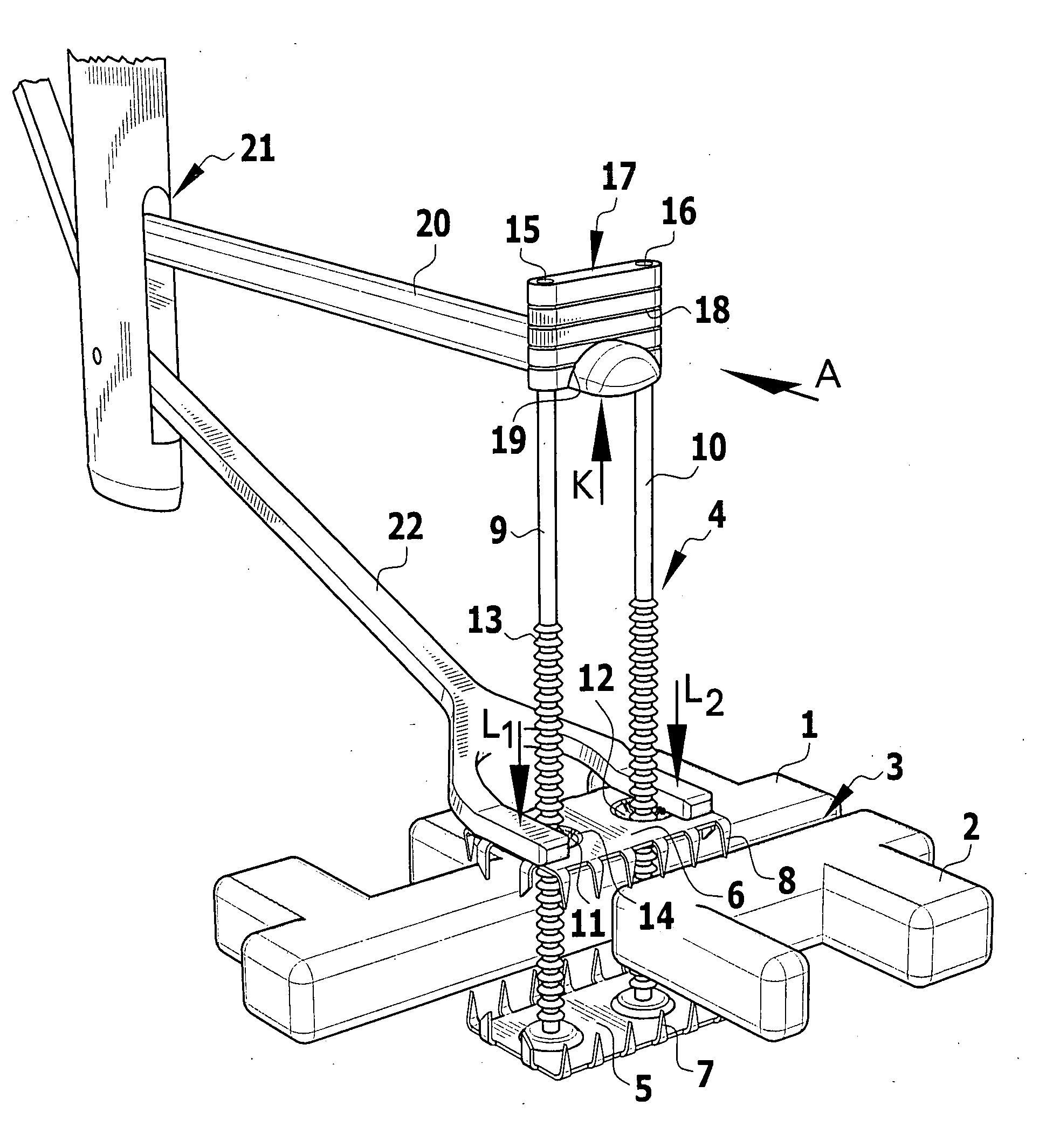
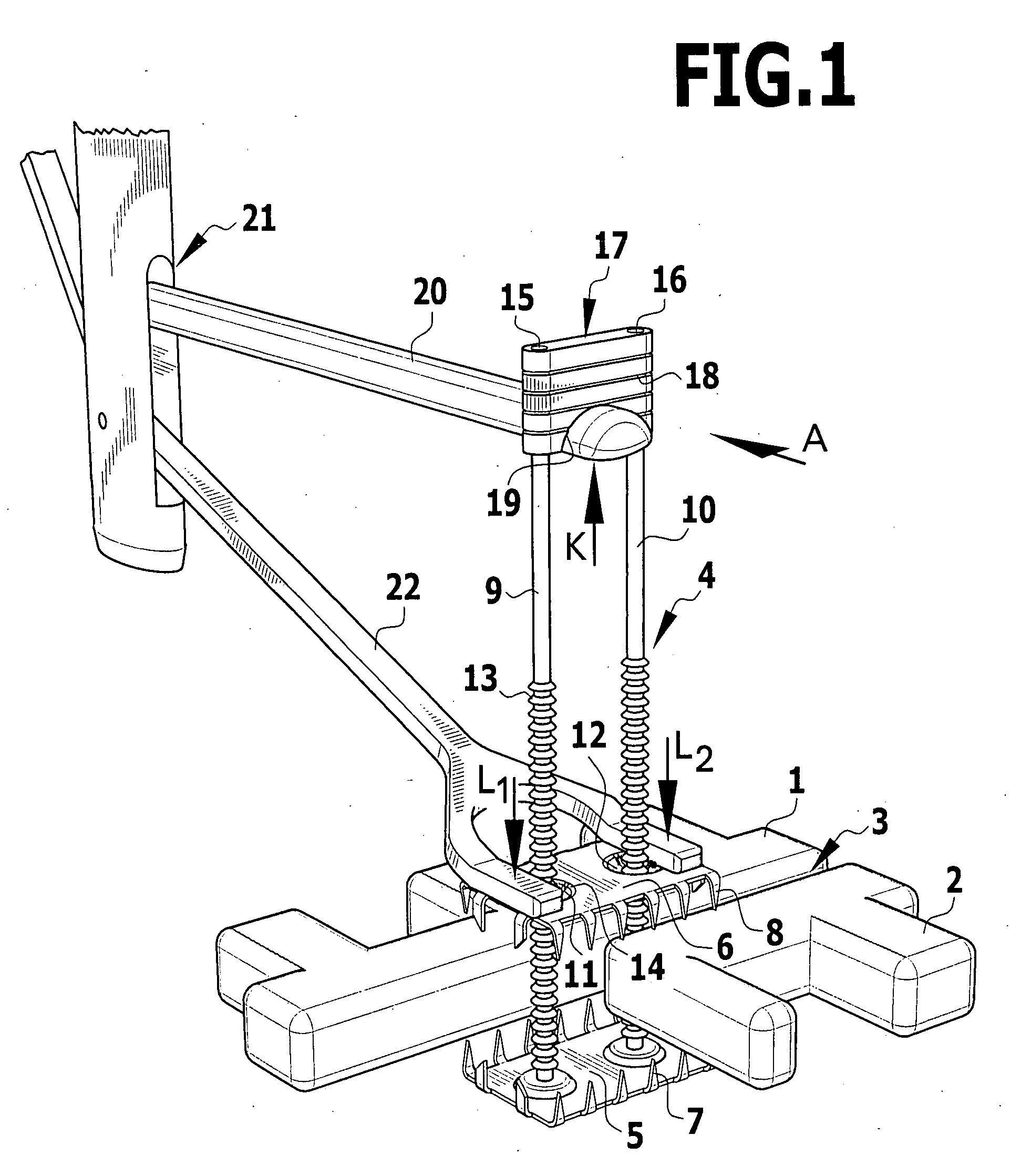
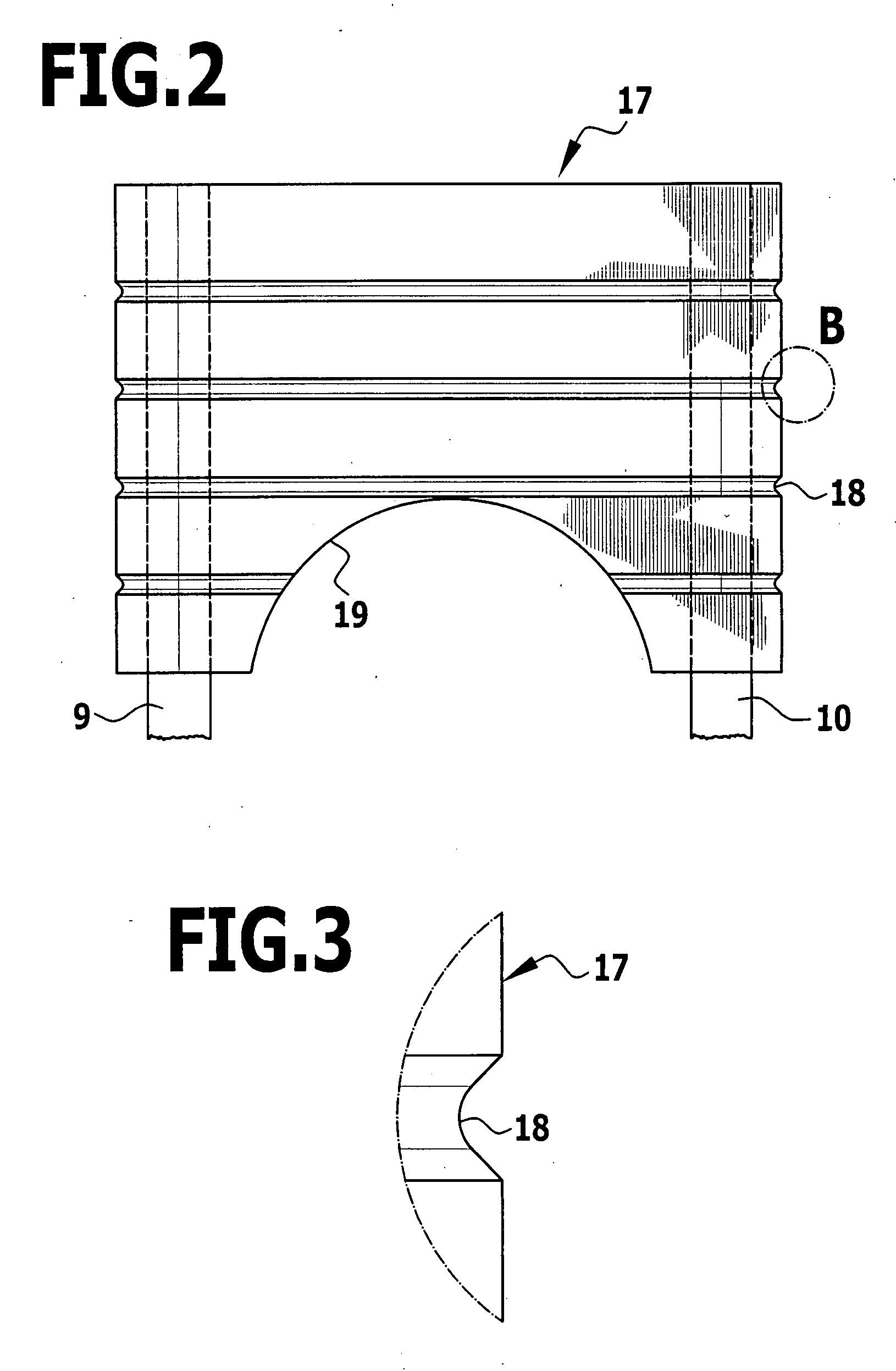
[0022] The two bone parts 1, 2 to be connected to each other may be, for example, two plate-shaped parts of the cranial bone or the parts of the costal arches separated from each other in a heart operation, which are separated along the sternum. In the case of the exemplary embodiment represented, the bone parts 1, 2 are schematically represented in a very simplified form; all that is important is that the bone parts 1, 2 are to be fixed in ...


PUM


Abstract

An implant for fixing two bone parts to be connected to each other is provided. The implant includes a first plate-shaped engaging element for engaging inner surfaces of the bone parts, at least two tensioning elements fixed on the engaging element and projecting transversely from it, and a second plate-shaped engaging element for engaging outer surfaces of the bone parts. The second engaging element can be tensioned with respect to the first engaging element by means of the tensioning elements brought through the interspace between the bone parts. To improve the ease of handling of the implant during tensioning, it is proposed that the tensioning elements are connected to each other at their end opposite from the first engaging element by a bridge.

Description

[0001] This application claims the benefit of German patent application no. 10 2006 021 024.7 filed on Apr. 28, 2006, which is incorporated herein and made a part hereof by reference. BACKGROUND OF THE INVENTION [0002] The invention relates to an implant for fixing two bone parts to be connected to each other, with a first plate-shaped engaging element for engaging inner surfaces of the bone parts, with at least two tensioning elements, fixed on said engaging element and projecting transversely from it, and with a second plate-shaped engaging element for engaging outer surfaces of the bone parts, which can be tensioned with respect to the first engaging element by means of the tensioning elements brought through the interspace between the bone parts. [0003] Such an implant is described for example in DE 103 26 690 B4. The engaging elements are in this case of a rectangular form and are tensioned with respect to each other by two tensioning elements in the form of pins, which project...

Claims


Application Information

Patent Timeline
IPC IPC(8): A61B17/84
CPCA61B17/688A61B17/8872A61B17/8869A61B17/823
Inventor MORALES, PEDROWEISSHAUPT, DIETERDWORSCHAK, MANFREDLUTZE, THEODOR
Owner AESCULAP AG
Why Eureka
Try Eureka