Motorized system and method of control

a motorized system and control method technology, applied in the direction of program control, electric programme control, instruments, etc., can solve the problems of increasing the speed and/or accuracy requirements of higher speed and/or accuracy, affecting the accuracy of generated commanded path matching the desired path description, and other undesirable effects, so as to reduce the acceleration rate

Active Publication Date: 2007-12-06
ORMON CORP
View PDF2 Cites 24 Cited by
  • Summary
  • Abstract
  • Description
  • Claims
  • Application Information

AI Technical Summary

Benefits of technology

[0007]FIG. 1 shows a graph 100 of the resulting position-versus-time 102 and velocity-versus-time 104 profiles for a simple constant-speed move passed through a digital filter with a 100-msec time constant, in a prior art system.
[0010]FIG. 2 shows a graph 200 of the commanded path of two runs of a shape composed of lines and arcs, in a prior art system. The first run 202 is executed without any acceleration control, and so produces the desired path precisely (although in a physically unrealizable manner). It produces the sharp corners and the outer arc paths in the graph. The second run 204 repeats the profile, but with a digital low-pass filter with Tf=100 msec applied after the interpolation. This is a very large time constant for the speed and size in order to produce easily seen effects. The corners are rounded significantly (and asymmetrically) so they can be passed without slowing, and the arcs fail significantly to the inside due to the filtering.
[0012]FIG. 4 shows a graph 400 of the same programmed path as in FIG. 2, with the first run 402 again going without acceleration control, but with the second run 404 utilizing a 100 msec acceleration time between moves applied before interpolation in a non-causal algorithm (using information about the subsequent trajectory). This method has the same peak accelerations as the method of FIG. 2, but the effect on path fidelity is much smaller. The corner rounding is much smaller, and the arcs do not fail to the inside. This method requires significantly more complex acceleration-calculation algorithms, particularly when applied to circular interpolation, but it does create superior path generation.
[0013]While the second method looks significantly superior, is it has some important disadvantages. First, it produces some undesirable effects when interactive feedrate override is used, as explained below. Second, it is more difficult in this method to apply acceleration control when the acceleration or deceleration must be applied over multiple programmed moves, such as when the moves are very small in complex contouring applications.

Problems solved by technology

Third, algorithms must keep the path traversal within the physical capabilities of the machine, usually expressed as limits on the higher time derivatives of motor position, particularly acceleration.
One problem with existing systems is that most implementations of acceleration and override control have significant adverse effects on the accuracy with which the generated commanded path matches the desired path description.
These effects were often tolerable at standard machining speeds and accuracies of the day, but become unacceptable at higher speeds and / or higher accuracy requirements.
Many other techniques that mitigate these effects produce other undesirable effects, such as delays in responding to override changes.
At now-common speeds and time constants, the resulting errors can be significant.
It is noteworthy that these are errors in the commanded path, and can occur well within the servo system's bandwidth; tracking errors of the servo loop as the bandwidth is exceeded can yield further errors.
First, it produces some undesirable effects when interactive feedrate override is used, as explained below.
Second, it is more difficult in this method to apply acceleration control when the acceleration or deceleration must be applied over multiple programmed moves, such as when the moves are very small in complex contouring applications.
But with feedrate or speed override control, the numerical increment can deviate from the real time.
This leads to substantially sub-optimum performance at low override values, and can lead to significant acceleration limit violations at override values greater than 100%, with the acceleration varying more widely with override than with the post-interpolation acceleration filter.
Nonetheless, important disadvantages remain.

Method used


Image

  • Motorized system and method of control
  • Motorized system and method of control
  • Motorized system and method of control

Examples


Embodiment Construction

[0024]A preferred embodiment of the invention incorporates a multiple-step process to generate a commanded path or trajectory with the desired properties from basic move descriptions, which are essentially defined by the nominally desired path to be followed by the tool. The term path is used to encompass both multi-dimensional and single dimensional patterns of motion or trajectorys.

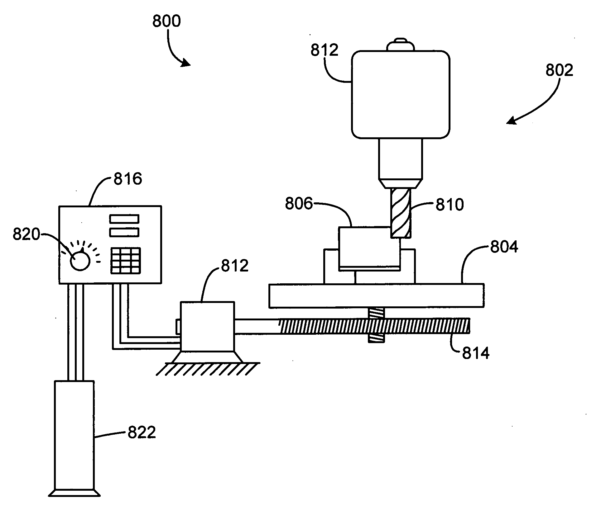
[0025]As shown in FIG. 8, the first step 710 reads a move description of each commanded move of the tool-tip relative to the workpiece and generates equations of motion for each axis consistent with the description. In CNC machining, moves are commonly described in RS-274 “G-codes”, but many other methods are possible.

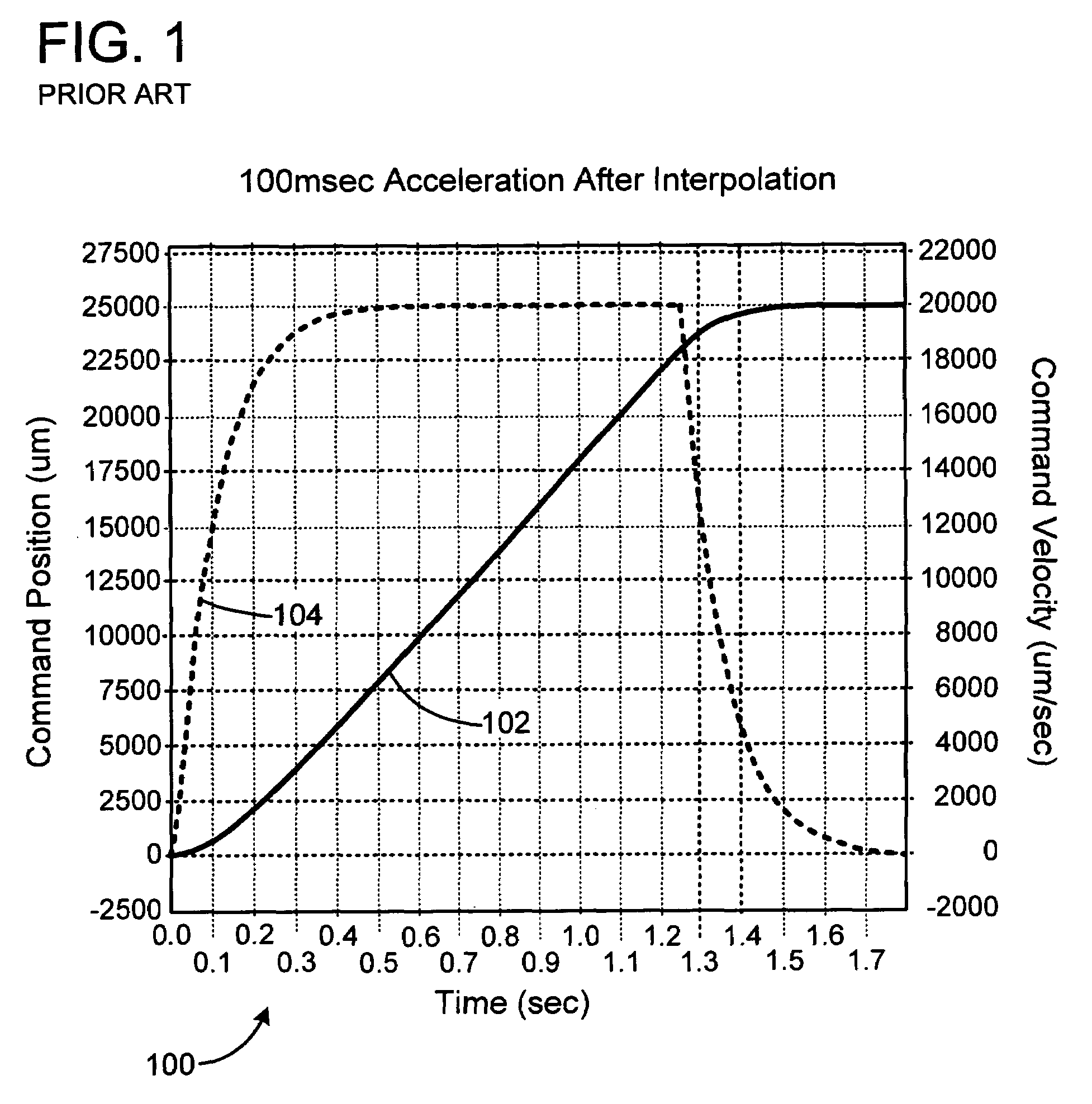
[0026]The second step 712 solves these equations at successive time intervals that are greater than the final setpoint-generation interval. This step is called “coarse interpolation”. Each generated point has a location, velocity, acceleration, and higher derivative properties. Feedrate ov...


PUM


Abstract

A system and method for generating a controlled motion path with a machine-tool system having a controller operating in a servo rate. The method includes a first interpolation step, in which a path segment corresponding to a number of servo update periods is calculated. After the first interpolation step, a speed override factor is established. After establishing the speed override factor a second interpolation step occurs, which includes calculating a number of path setpoints for each path segment. The number of servo update periods per path segment may vary over the path.

Description

FIELD OF THE INVENTION[0001]This invention relates to computer controlled machine tools and other similar devices that provide automated motion or path control.BACKGROUND AND SUMMARY OF THE INVENTION[0002]In many path-based automatic positioning applications, such as computer numerically controlled (CNC) machining, the controller's commanded path-generation algorithms need to satisfy many user desires simultaneously. First, they must follow the desired path within a certain required positional accuracy. Second, where possible, they must follow this path at a programmed vector tool speed, or “feedrate” (the rate at which the material is fed into the tool, or at which the tool is moved through the material). Third, algorithms must keep the path traversal within the physical capabilities of the machine, usually expressed as limits on the higher time derivatives of motor position, particularly acceleration. Finally, in many systems, the operator must be given an interactive “feedrate ov...

Claims


Application Information

Patent Timeline
Patent Type & Authority Applications(United States)
IPC IPC(8): G05B19/25
CPCG05B19/25
Inventor WILSON, CURTIS
Owner ORMON CORP
Why Eureka
Try Eureka