Multi-Mode Antenna Array

a multi-mode, antenna array technology, applied in the direction of antennas, antenna details, simultaneous aerial operations, etc., can solve the problems of narrow beam shape, inability to communicate with the antenna, and large range of null areas in which the antenna cannot communicate, so as to achieve greater communication range and expand the range of communication for the tag

Inactive Publication Date: 2007-12-06
MARK IV IVHS
View PDF5 Cites 83 Cited by
  • Summary
  • Abstract
  • Description
  • Claims
  • Application Information

AI Technical Summary

Benefits of technology

[0008]By configuring the tag antenna to have multiple narrower beam patterns of divergent directivity, the antenna provides for an extensive communications range through a broad spectrum of orientations. Even though, for a given orientation, the tag may not be capable of communicating at all resonant frequencies, it may be capable of communicating with at least one of its resonant frequencies. The more focused directivity of the radiation pattern for a given frequency means that the range of communication for the tag is greater than would be possible using the equivalent dipole antenna

Problems solved by technology

However, this results in a larger range of null areas in which the antenna cannot communicate.
Accordingly, narrow beam shape is typically not desirable for RFID applications, since RFID tags may often be oriented in any random position relative to a reader,

Method used


Image

  • Multi-Mode Antenna Array
  • Multi-Mode Antenna Array
  • Multi-Mode Antenna Array

Examples


Embodiment Construction

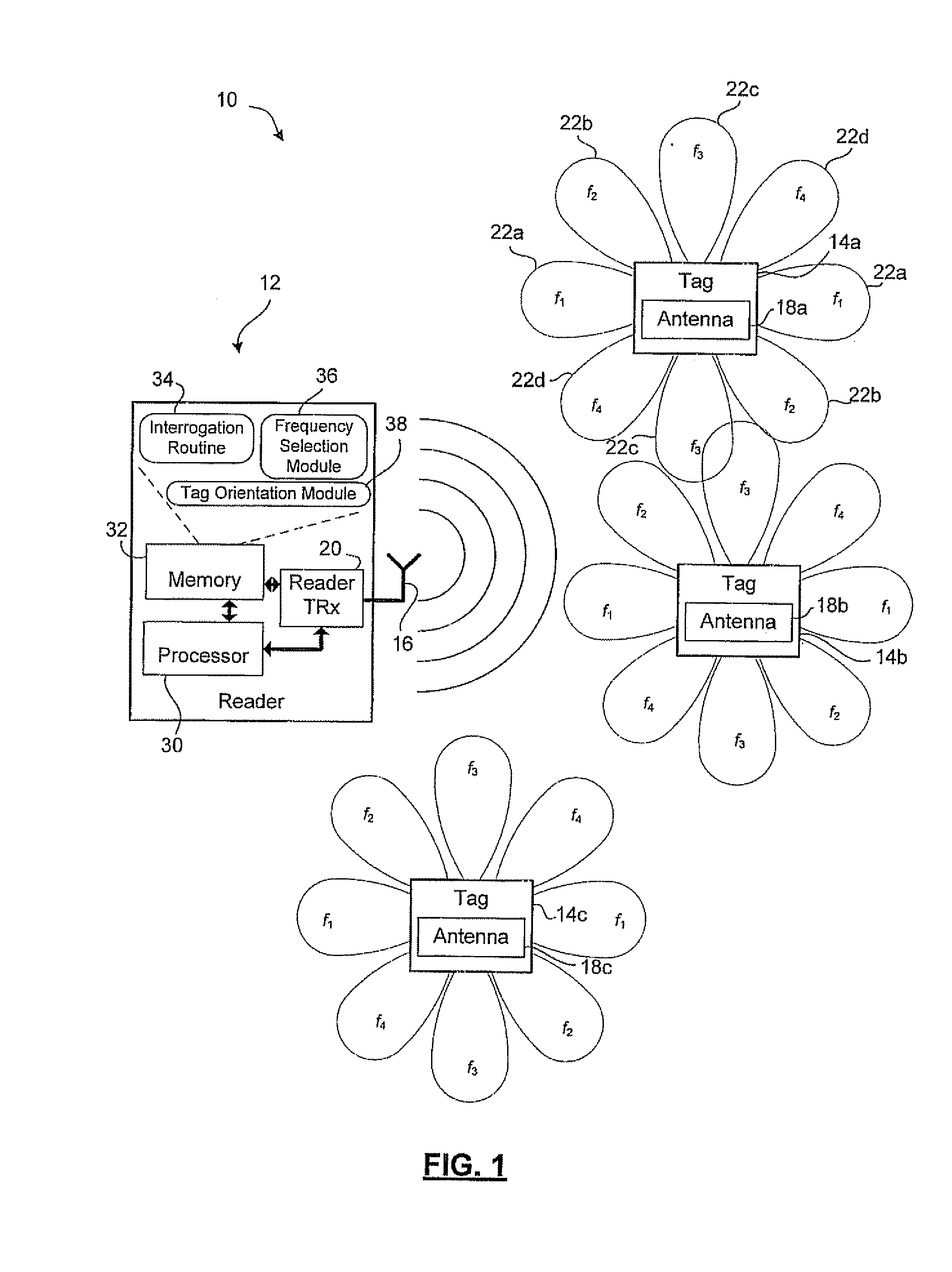
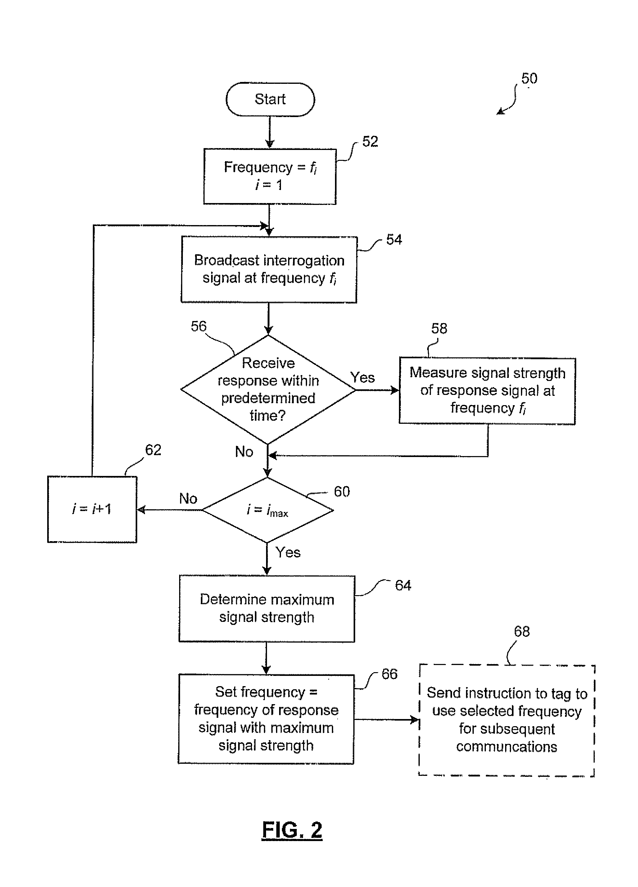
[0032]Reference is first made to FIG. 1, which shows an example embodiment of an RFID system 10 according to the present description The system 10 includes a reader 12 and a plurality of tags 14 (shown individually as 14a, 14b, and 14c). The reader 12 and the tags 14 communicate using RF signals In some embodiments the each tag 14 may be attached to or associated with consumer products such as individual articles of clothing, accessories, consumer electronics, household items, etc. The tags 14 may store data regarding the item with which they are associated For example, in some embodiments the tags 14 may store information that conforms to Electronic Product Code (EPC) standards regarding product identification Nevertheless, the present RFID system 10 is not limited to use in connection with tracking inventory items and may be used in any other application of RFID technology

[0033]The reader 12 includes a transceiver 20 and a reader antenna 16. The transceiver 20 and reader antenna 1...


PUM


Abstract

A multi-mode parasitic antenna array having two or more resonant frequencies. The multi-mode parasitic antenna array has at least two resonant modes resulting in substantially divergent radiation patterns, thereby providing the antenna with frequency dependent directivity. The array may be incorporated into a tag for an RFID system. The RFID system includes a reader capable of interrogating the tag at each of the resonant frequencies.

Description

FIELD OF THE INVENTION[0001]The present invention relates to radio frequency (RF) antennas and, in particular, a steerable multi-mode antenna array and radio frequency identification tags and systems incorporating the antenna array.BACKGROUND OF THE INVENTION[0002]Radio frequency identification (RFID) technology is now being used to track a wide variety of items. In many RFID systems, the tag may be located in any direction and may be in any orientation, so the tag antenna preferably has a nearly omni-directional radiation pattern. The most simple antenna design used in creating a cost-effective tag antenna is a dipole. A simple dipole antenna features a toroidal radiation pattern at its resonant frequency, meaning that the antenna gain and sensitivity is diversely spread over a wide beam shape. The toroidal pattern also features a null point at either axial end of the dipole.[0003]In order to increase the sensitivity and range of an antenna, the antenna may be designed to have a na...

Claims


Application Information

Patent Timeline
Patent Type & Authority Applications(United States)
IPC IPC(8): H01Q1/38H01Q5/10
CPCH01Q9/0407H01Q19/005H01Q9/0442
Inventor COUTTS, GORDONMANSOUR, RAAFATCHAUDHURI, SUJEETTANG, WAI-CHEUNG
Owner MARK IV IVHS
Why Eureka
Try Eureka