System and method for measuring distribution quality of video image

a video image and distribution quality technology, applied in the field of system and a method for measuring the distribution quality of video images, can solve the problems of packet loss at a time of convergence, difficulty in achieving image distribution service in a conventional narrowband network, and packet loss

Inactive Publication Date: 2007-12-06
NEC CORP
View PDF10 Cites 10 Cited by
  • Summary
  • Abstract
  • Description
  • Claims
  • Application Information

AI Technical Summary

Benefits of technology

[0011]Therefore, the present invention provides a measuring system and a measuring method, in which a distribution quality of packets can be measured without performing any process on the packets.
[0012]In an exemplary aspect of the present invention, a measuring system of video image distribution quality includes a distribution server, a receiving terminal, an upstream side reception time data generating section, a downstream side reception time data generating section and a quality data measuring section. The distribution server is provided in a center to transmit packets for a video image through a network, and the receiving terminal is provided in a user home to receive the packets transmitted through the network from the distribution server. The upstream side reception time data generating section is provided in the center to generate an upstream side reception time data indicating a time when the distribution server transmits one of the packets. The downstream side reception time data generating section is provided for the user home to generate a downstream side reception time data indicating a time when the receiving terminal receives the packet. The quality data measuring section is provided for one of the center and the user home, to measure a distribution quality indicating a distribution state from the distribution server to the receiving terminal based on the upstream side reception time data and the downstream side reception time data.
[0013]In another exemplary aspect of the present invention, a measuring apparatus used in a distribution quality measuring system comprising a distribution server provided in a center to transmit packets for a video image to a network, and a receiving terminal provided in a user home to receive the packets transmitted through the network from the distribution server. The measuring apparatus includes an upstream side reception time data generating section provided for the center to generate and transmit an upstream side reception time data indicating a time when the distribution server transmits each of the packets; a downstream side reception time data generating section provided for the user home to generate and transmit a downstream side reception time data indicating a time when the receiving terminal receives each of the packets; and a quality data measuring section provided for one of the center and the user home to measure distribution quality of the packets distributed from the distribution server to the receiving terminal based on the upstream side reception time data and the downstream side reception time data.
[0014]Also, in another exemplary aspect of the present invention, a method of measuring a distribution quality, is achieved by transmitting packets for a video image to a network from a distribution server provided in a center; by receiving the packets transmitted through the network from the distribution server by a receiving terminal provided in a user home; by generating an upstream side reception time data indicating a time when the distribution server transmits each of the packets, by an upstream side reception time data generating section provided for the center; by generating a downstream side reception time data indicating a time when the receiving terminal receives each of the packets, by a downstream side reception time data generating section provided for the user home; and by measuring distribution quality of the packets distributed from the distribution server to the receiving terminal based on the upstream side reception time data and the downstream side reception time data, by a quality data measuring section provided for one of the center and the user home.

Problems solved by technology

It is difficult to attain this image distribution service in a conventional narrowband network.
However, the video image distributing service has the following problems.
In the image distribution, there may be a case that a phenomenon that some of packets of the video image data are lost or the packets do not arrive within a predetermined time period.
In particular, IP of the protocol of a network layer which is used currently widely has a possibility that a packet loss occurs at a time of convergence, because of its specification.
In this way, as the load becomes heavy, it is difficult to employ this countermeasure for the distribution to the many users.
Also, there is no insurance with regard to a transmission delay.
Hence, there is a possibility that a great variation is generated in the transmission delay.

Method used


Image

  • System and method for measuring distribution quality of video image
  • System and method for measuring distribution quality of video image
  • System and method for measuring distribution quality of video image

Examples


first exemplary embodiment

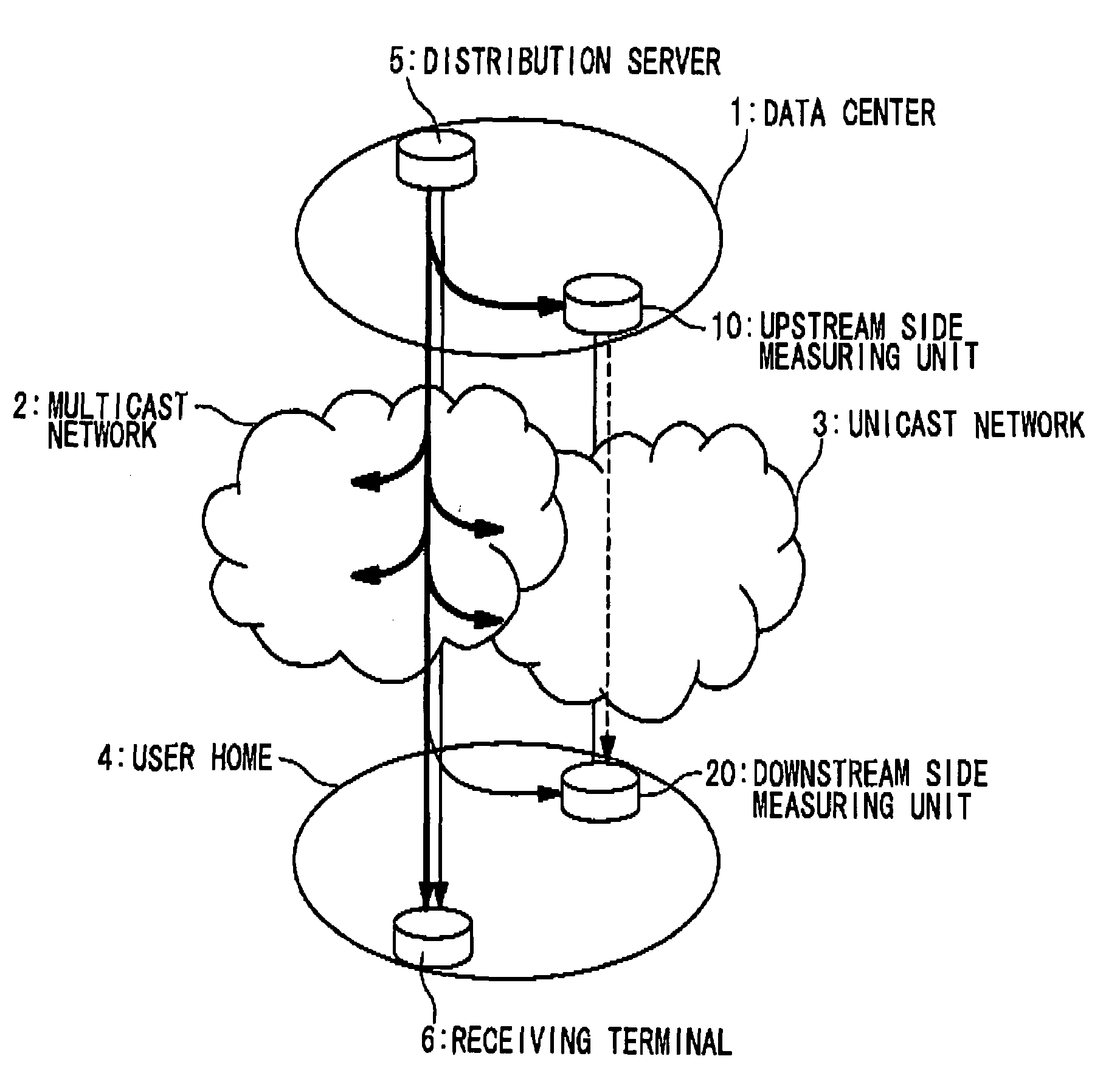
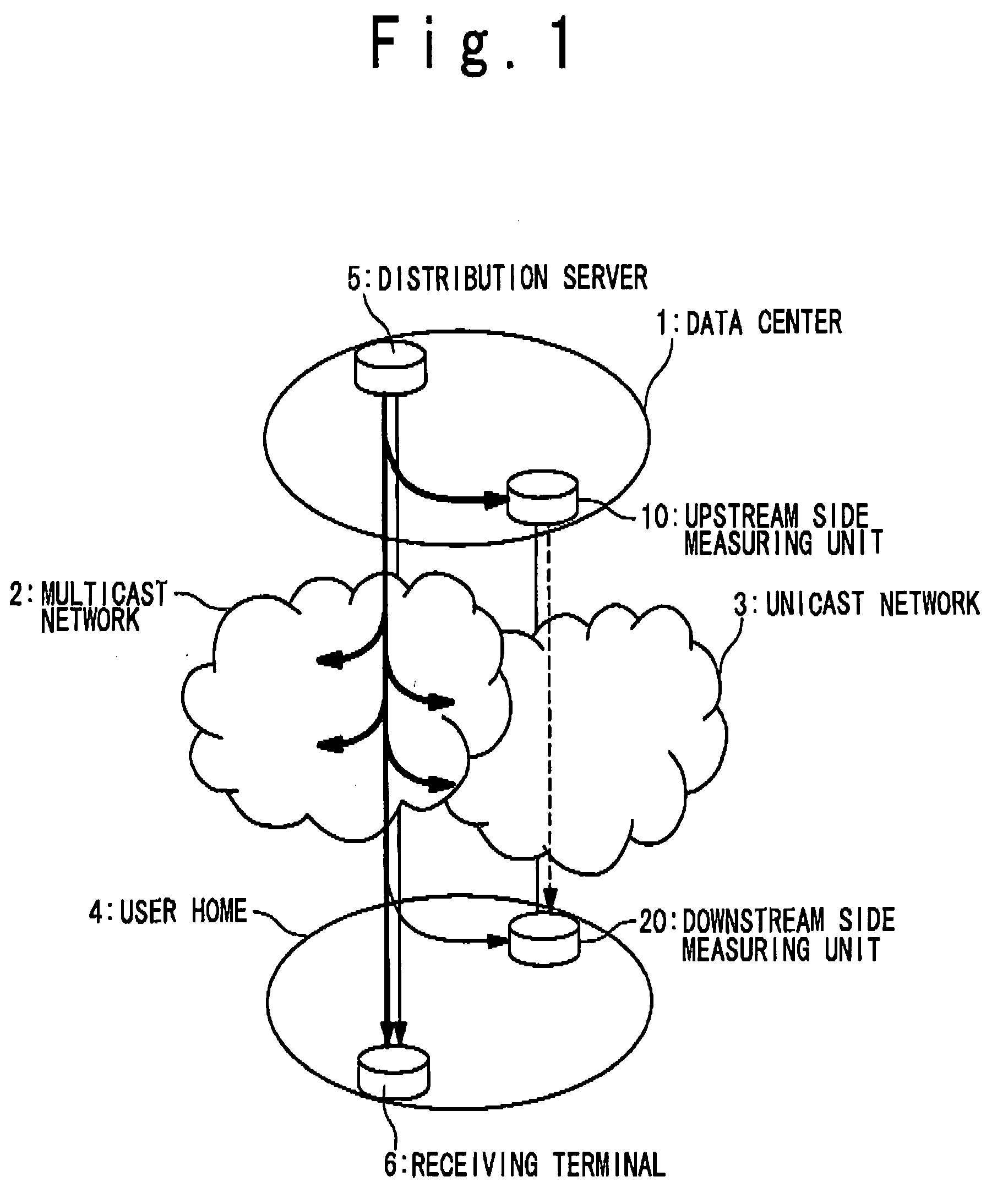
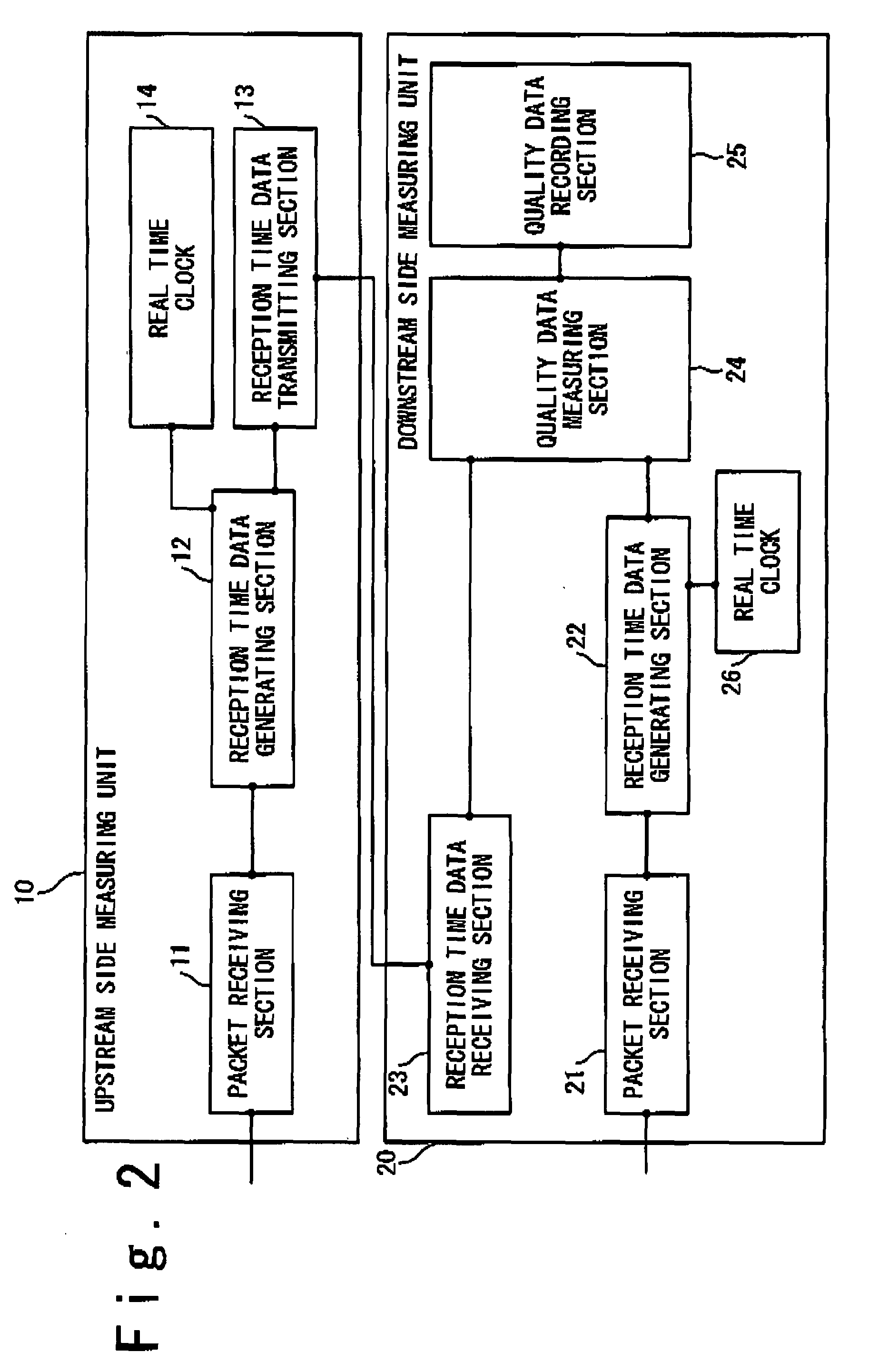
[0048]FIG. 1 shows a configuration of a measuring system of quality of distributed video image data according to a first exemplary embodiment of the present invention. Referring to FIG. 1, the measuring system according to the first exemplary embodiment contains a multicast network 2, a unicast network 3, a distribution server 5, a receiving terminal 6 and a measuring apparatus of quality of distributed vide image data. The distribution server 5, the receiving terminal 6 and the measuring apparatus may be computers. The measuring apparatus contains an upstream side measuring apparatus 10 and a downstream side measuring apparatus 20. The distribution server 5 and the upstream side measuring apparatus 10 are installed in a data center 1. The upstream side measuring apparatus 10 is connected to the distribution server 5 in the data center 1. The distribution server 5 in the data center 1 transmits packets of video image data to the multicast network 2. Each packet (multicast packet) tr...

second exemplary embodiment

[0104]In an image distribution quality measuring system according to a second exemplary embodiment of the present invention, the same description as the second exemplary embodiment is omitted. FIG. 16 is a block diagram showing the configuration of the upstream side measuring apparatus 10 and the downstream side measuring apparatus 20. In FIG. 16, the illustration of the unicast network 3 is omitted.

[0105]The upstream side measuring apparatus 10 further contains an upstream side hash value generating section 15 as a function block. The hash value generating section 15 is connected to the packet receiving section 11 and the reception time data generating section 12. The downstream side measuring apparatus 20 contains a hash value quality data measuring section 24a instead of the quality data measuring section 24. The downstream side measuring apparatus 20 further contains a downstream side hash value generating section 27 as a function block. The hash value generating section 27 is c...

third exemplary embodiment

[0119]In the measuring system according to a third exemplary embodiment of the present invention, the same descriptions as those of the above exemplary embodiments are omitted.

[0120]FIG. 23 shows the configuration of the measuring system according to the third exemplary embodiment of the present invention. In the first exemplary embodiment, the upstream side reception time data 60 is transmitted from the upstream side measuring apparatus 10 to the downstream side measuring apparatus 20. On the contrary, the third exemplary embodiment differs from it in that the downstream side reception time data 60 is transmitted from the downstream side measuring apparatus 20 to the upstream side measuring apparatus 10.

[0121]FIG. 24 is a block diagram showing the configuration of the upstream side measuring apparatus 10 and the downstream side measuring apparatus 20. In FIG. 24, the illustration of the unicast network 3 is omitted.

[0122]The upstream side measuring apparatus 10 contains the packet ...


PUM


Abstract

A measuring system of distribution quality of a video image includes a distribution server, an receiving terminal, an upstream side reception time data generating section, a downstream side reception time data generating section and a quality data measuring section. The distribution server is provided in a center to transmit packets for a video image through a network, and the receiving terminal is provided in a user home to receive the packets transmitted through the network from the distribution server. The upstream side reception time data generating section is provided in the center to generate an upstream side reception time data indicating a time when the distribution server transmits one of the packets. The downstream side reception time data generating section is provided for the user home to generate a downstream side reception time data indicating a time when the receiving terminal receives the packet. The quality data measuring section is provided for one of the center and the user home, to measure a distribution quality indicating a distribution state from the distribution server to the receiving terminal based on the upstream side reception time data and the downstream side reception time data.

Description

CROSS REFERENCE[0001]This application is based upon and claims the benefit of priority from Japanese patent application No. 2006-149959, filed on May 30, 2006. Also, this application relates to the U.S. patent application Ser. No. ______, titled “PACKET DISTRIBUTION SYSTEM USING REPRODUCING APPARATUS AND PACKET DISTRIBUTION METHOD” by Kazuya SUZUKI and Masahiro JIBIKI, claiming the priority based on Japanese Patent Application No. 2006-149960 filed on May 30, 2006. The disclosures of these applications are incorporated herein by reference.TECHNICAL FIELD[0002]The present invention relates to a system and a method for measuring distribution quality of a video image.BACKGROUND ART[0003]A video image distribution service for distributing a video image data through a network has been spread widely. In recent years, a video image distribution service for distributing a video image data in a higher quality than the foregoing video image data has been developed. It is difficult to attain t...

Claims


Application Information

Patent Timeline
Patent Type & Authority Applications(United States)
IPC IPC(8): H04J1/00H04L12/70H04N21/235H04N7/173H04N21/24H04N21/435
CPCH04N7/17309H04N17/004H04N21/2402H04N21/44209H04L65/80H04N21/6408H04N21/6582H04L65/4076H04L65/4084H04N21/6405H04L65/611H04L65/612
Inventor SUZUKI, KAZUYAJIBIKI, MASAHIRO
Owner NEC CORP
Why Eureka
Try Eureka