Transmitter and transmission method

a transmission method and transmitter technology, applied in the direction of orthogonal multiplex, multiplex communication, transmission path division, etc., can solve the problems of high roll-off rate, steep band limitation, and need to perform band limitation, and achieve the effect of improving frequency utilization efficiency and large siz

Inactive Publication Date: 2007-12-06
FUJITSU LTD
View PDF5 Cites 70 Cited by
  • Summary
  • Abstract
  • Description
  • Claims
  • Application Information

AI Technical Summary

Benefits of technology

[0028]The present invention is made in view of the foregoing and other problems. An object of the present invention is therefore to provide a transmitter and a transmission method that allow for improvement in frequency utilization efficiency (data transmission efficiency) without the need for a plurality of time / frequency-domain conversion circuits with a large size such as DFTs.

Problems solved by technology

With this method, it is difficult to perform steep band limitation and thus there is a need to perform band limitation by an FIR filter with a high roll-off rate.
In the DFT-S-OFDM, a DFT computation processing is required and thus generally there is a problem of an increase in circuit size.
If an FFT whose number of points is a power of two can be used for a DFT, a significant reduction in circuit size is achieved; however, in practice, since parameters are designed to obtain optimum frequency utilization efficiency and PAPR characteristics, the DFT size is not always a power of two.
Thus, in the DFT-S-OFDM scheme, there is a tendency that the circuit size increases.
However, as described above, there is a problem that the circuit size of a DFT is large as compared with that of an FFT.
Thus, in the case where the DFT size is changed according to the modulation scheme, a plurality of types of DFT circuits with a large size need to be provided on hardware, further increasing the impact of circuit size.

Method used


Image

  • Transmitter and transmission method
  • Transmitter and transmission method
  • Transmitter and transmission method

Examples


first embodiment

(A) Description of a First Embodiment

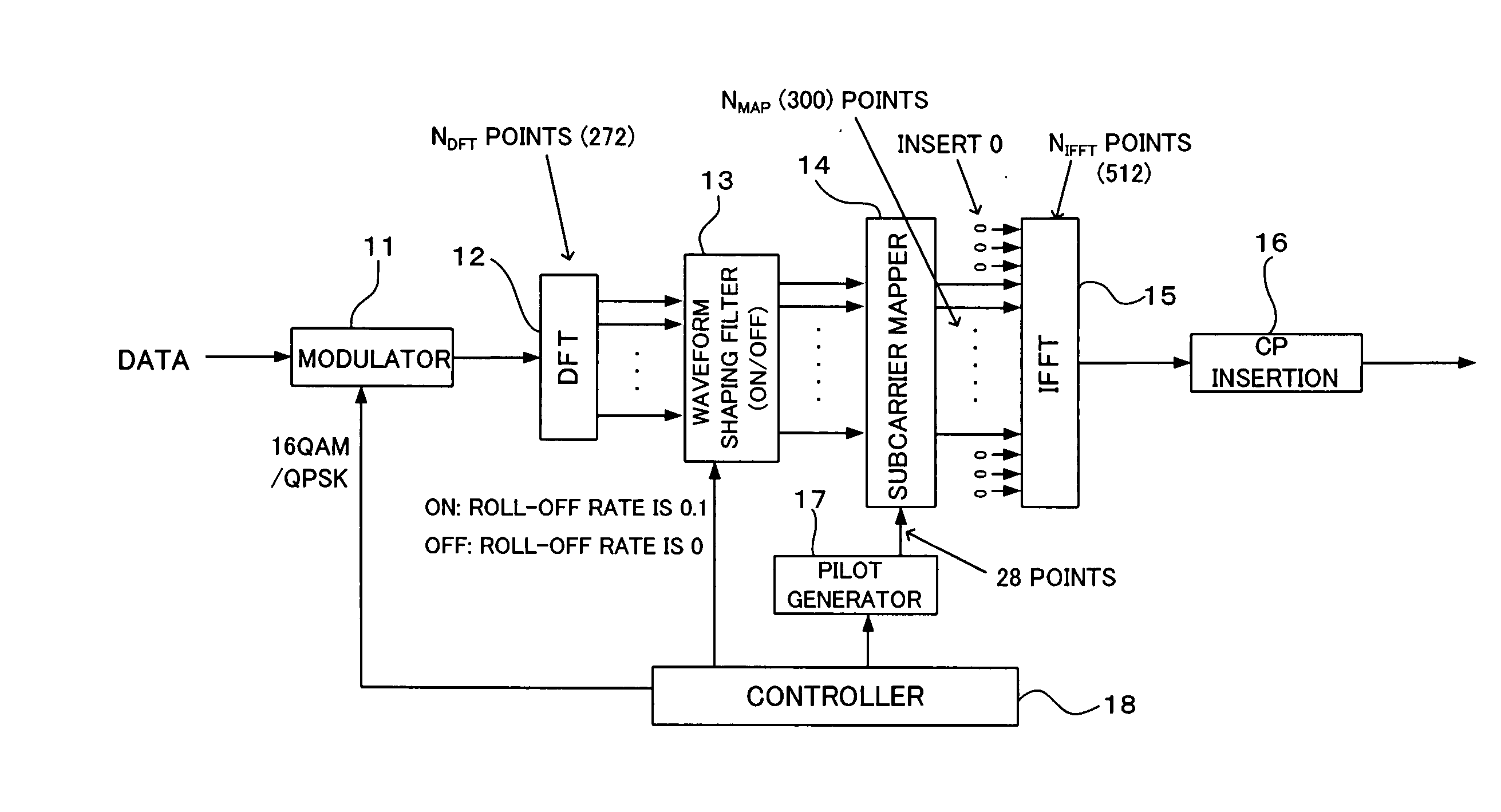
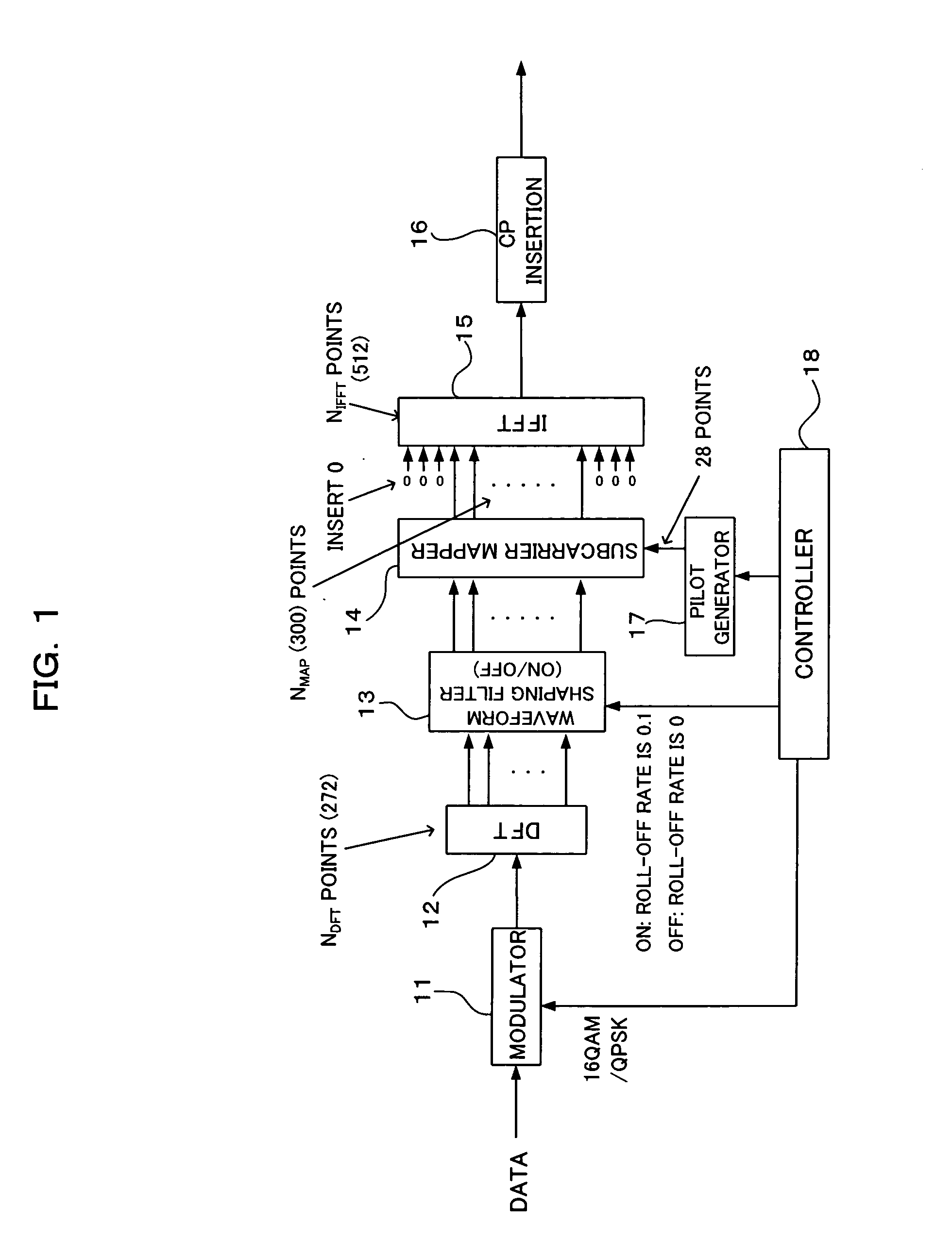
[0064]FIG. 1 is a block diagram showing a configuration of an essential part of a DFT-S-OFDM transmitter according to a first embodiment of the present invention. ADFT-S-OFDM transmitter (hereinafter also simply referred to as the “transmitter”) shown in FIG. 1 can be applied, as will be described later in FIG. 3, for example, to a mobile station apparatus that adopts the DFT-S-OFDM scheme for at least an uplink in a mobile communication system. The DFT-S-OFDM transmitter includes a modulator 11, a DFT 12, a waveform shaping filter 13, a subcarrier mapper 14, an IFFT 15, a CP inserter 16, a pilot generator 17, and a controller 18.

[0065]The modulator 11 modulates a data-channel data (symbols) to be transmitted (hereinafter also referred to as a “data channel signal” or “data signal”) by a required modulation scheme such as QPSK or 16 QAM. In the present example, the modulation scheme can be adaptively changed by control from the controller 18.

[006...

second embodiment

(B) Description of a Second Embodiment

[0117]FIG. 5 is a block diagram showing a second embodiment of the DFT-S-OFDM transmitter described above in FIG. 1. The transmitter shown in FIG. 5 can also be applied to a transmission system of an MS 1, as in the configuration shown above in FIG. 3. The configuration shown in FIG. 5 is different from that shown in FIG. 1 in that the waveform shaping filter 13 is eliminated and a PAPR reduction pattern / pilot generator 22 and a controller 24 are provided in place of the pilot generator 17 and the controller 18, and a PAPR measure 23 is additionally provided. Note that in FIG. 5 elements denoted by the same reference numerals as those described above represent the same or similar elements as / to those described above, unless otherwise specified.

[0118]The PAPR reduction pattern / pilot generator (PAPR reduction signal generation means and pilot signal generation means) 22 generates a signal (symbols) (hereinafter referred to as a “PAPR reduction sig...


PUM


Abstract

A transmitter includes a time/frequency-domain converter that converts a time-domain data signal to a frequency-domain data signal of a fixed number; a subcarrier allocator that allocates the obtained frequency-domain data signal to any of subcarriers, the number of which exceeds the fixed number, the subcarriers being allocated in a predetermined transmission frequency band; and a controller that controls the subcarrier allocator to allocate signals other than the data signal to subcarriers in an idle band to which the data signal is not allocated. By this, without the need for a plurality of time/frequency-domain conversion circuits with a large size, such as DFTs, frequency utilization efficiency (data transmission efficiency) is improved.

Description

CROSS REFERENCE TO RELATED APPLICATIONS[0001]This application is based on and hereby claims priority to Japanese Application No. 2006-157610 filed on Jun. 6, 2006 in Japan, the contents of which are hereby incorporated by reference.BACKGROUND OF THE INVENTION[0002](1) Field of the Invention[0003]The present invention relates to a transmitter and a transmission method. The present invention relates to a technique suitable for use in radio communication techniques such as mobile communication systems that use a DFT-S-OFDM (Discrete Fourier Transform-Spread-Orthogonal Frequency Division Multiplexing) scheme, for example.[0004](2) Description of Related Art[0005]At present, in 3GPP (3rd Generation Partnership Project), standardization of enhancement (Long Term Evolution) of third generation mobile communication systems is under consideration. For an uplink access scheme, adoption of SC-FDMA (Single Carrier-Frequency Division Multiple Access) is considered and a method of implementing th...

Claims


Application Information

Patent Timeline
Patent Type & Authority Applications(United States)
IPC IPC(8): H04K1/10
CPCH04B1/69H04L5/0007H04L27/2636H04L5/0048H04L27/2618H04L5/0046H04J2211/006H04L1/0003H04W72/0453
Inventor SEKI, HIROYUKI
Owner FUJITSU LTD
Why Eureka
Try Eureka