Process Cartridge and Image Forming Apparatus

a technology of image forming apparatus and process cartridge, which is applied in the direction of electrographic process apparatus, instruments, optics, etc., can solve the problems of reduced force, unsatisfactory operation, and reduced force, and achieves simple structure and high precision positioning.

Inactive Publication Date: 2007-12-06
CANON KK
View PDF4 Cites 8 Cited by
  • Summary
  • Abstract
  • Description
  • Claims
  • Application Information

AI Technical Summary

Benefits of technology

[0009] Accordingly, it is a principal object of the present invention to provide a process cartridge and an image forming apparatus, wherein a high precision positioning between the process cartridge and the main assembly of the image forming apparatus can be accomplished with a simple structure.

Problems solved by technology

However, the conventional image forming apparatus involves a problem in the operationality in the positioning and removal of the cartridge.
If the spring force is reduced, the resistance is reduced, but the positioning force is also reduced, and therefore, doing so is not desirable.
As a result, the cartridge may rise, or ride on another element, so that cartridge might not be positioned correctly.
This results in an excessive load applied to the photosensitive drum and to the transfer belt unit disposed opposed thereto, and may lead to damage in the belt within an image forming region thereof, and then, the image formation is adversely influenced.
To accomplish this, a rotation of the twisted hole is required to engage from the projection 616, and therefore, a rotation link mechanism is necessary which is interrelated with some operation, with the result of a complicated structure, and therefore, increase in the number of parts, in the cost and in the limitation to the arrangements of parts.

Method used


Image

  • Process Cartridge and Image Forming Apparatus
  • Process Cartridge and Image Forming Apparatus
  • Process Cartridge and Image Forming Apparatus

Examples


Embodiment Construction

[0022] Referring to FIG. 1 to FIG. 4, the description will be made as to the embodiments of the present invention. First, the description will be made as to a general arrangement of the main assembly of the image forming apparatus, and then as to the structure which improves the mounting property of the cartridge to the main assembly of the image forming apparatus, and finally as to the positioning of the cartridge and as to the structure of supporting means.

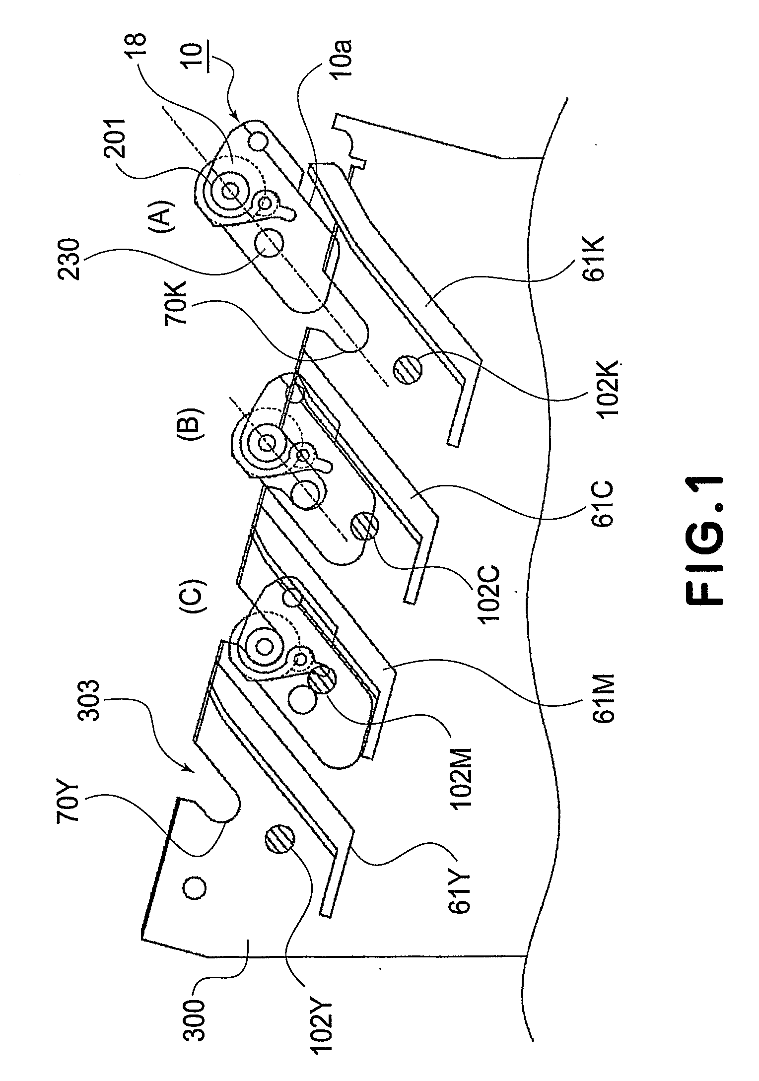
[0023]FIG. 3 is a schematic illustration of an example of a full-color image forming apparatus (full color printer) having an intermediary transfer belt (middle transferring means) of an in-line type, using an electrophotographic type process, wherein the righthand side is a front side of the apparatus.

[0024] The image forming apparatus 2 is loaded with four process cartridges 10 arranged in a substantially horizontal line at regular intervals, and the cartridges are for yellow color image formation (10Y), magenta color image ...


PUM


Abstract

A process cartridge detachably mountable to a main assembly of the image forming apparatus, the process cartridge includes an image bearing member; a developing device for developing an electrostatic image formed on the image bearing member with a developer; an image bearing member driving force input portion for receiving a driving force for rotating the image bearing member from an image bearing member driving force output portion from the main assembly; a developing device driving force input portion for receiving a driving force for driving the developing device from a developing device driving force output portion of the main assembly, wherein the image bearing member driving force output portion and the image bearing member driving force input portion are engaged with each other with a play in a mounting and demounting direction of the process cartridge, when the driving force is inputted from the image bearing member driving force output portion to the image bearing member driving force input portion, and wherein when the driving force is inputted from the developing device driving force output portion to the developing device driving force input portion, a part of the process cartridge is urged toward a positioning portion for positioning of the process cartridge relative to the main assembly.

Description

TECHNICAL FIELD [0001] The present invention relates to a process cartridge including process means for image forming operation, and an electrophotographic image forming apparatus for forming an image using the process cartridge. BACKGROUND ART [0002] In the field of an image forming apparatus using an electrophotographic image forming process, a process cartridge type is used wherein a photosensitive member and process means actable on the photosensitive member, such as charging means, developing means, cleaning means or the like) are unified into a cartridge which is detachably mountable to a main assembly of the image forming apparatus. The process cartridge type is advantageous in that maintenance of the apparatus can be carried out by the user of the apparatus without a service person, so that operationality is remarkably improved. Therefore, the process cartridge type is widely used in the field of the image forming apparatus. It is desirable that said process cartridge is mou...

Claims


Application Information

Patent Timeline
Patent Type & Authority Applications(United States)
IPC IPC(8): G03G21/18
CPCG03G15/757G03G21/186G03G2221/183G03G2221/1654G03G2221/1657G03G21/1864
Inventor KAWASUMI, RYOICHI
Owner CANON KK
Why Eureka
Try Eureka