Thermoplastic film and method of producing the same, polarizing plate, optical compensation film, antireflection film and liquid-crystal display device

a technology of thermoplastic film and anti-reflection film, which is applied in the direction of polarizing elements, transportation and packaging, chemistry apparatus and processes, etc., can solve the problems of inability to completely prevent the release of organic solvents, surface smoothness, accuracy fluctuation, etc., and achieve stable production, well-balanced condition, surface smoothness may worsen

Active Publication Date: 2007-12-06
FUJIFILM CORP
View PDF3 Cites 26 Cited by
  • Summary
  • Abstract
  • Description
  • Claims
  • Application Information

AI Technical Summary

Benefits of technology

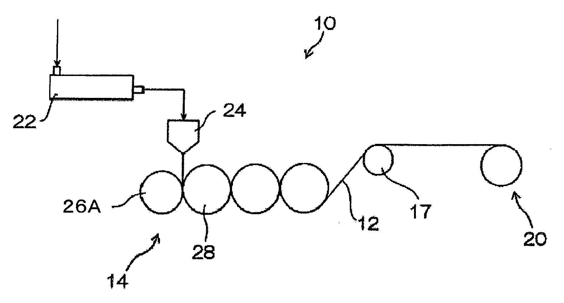
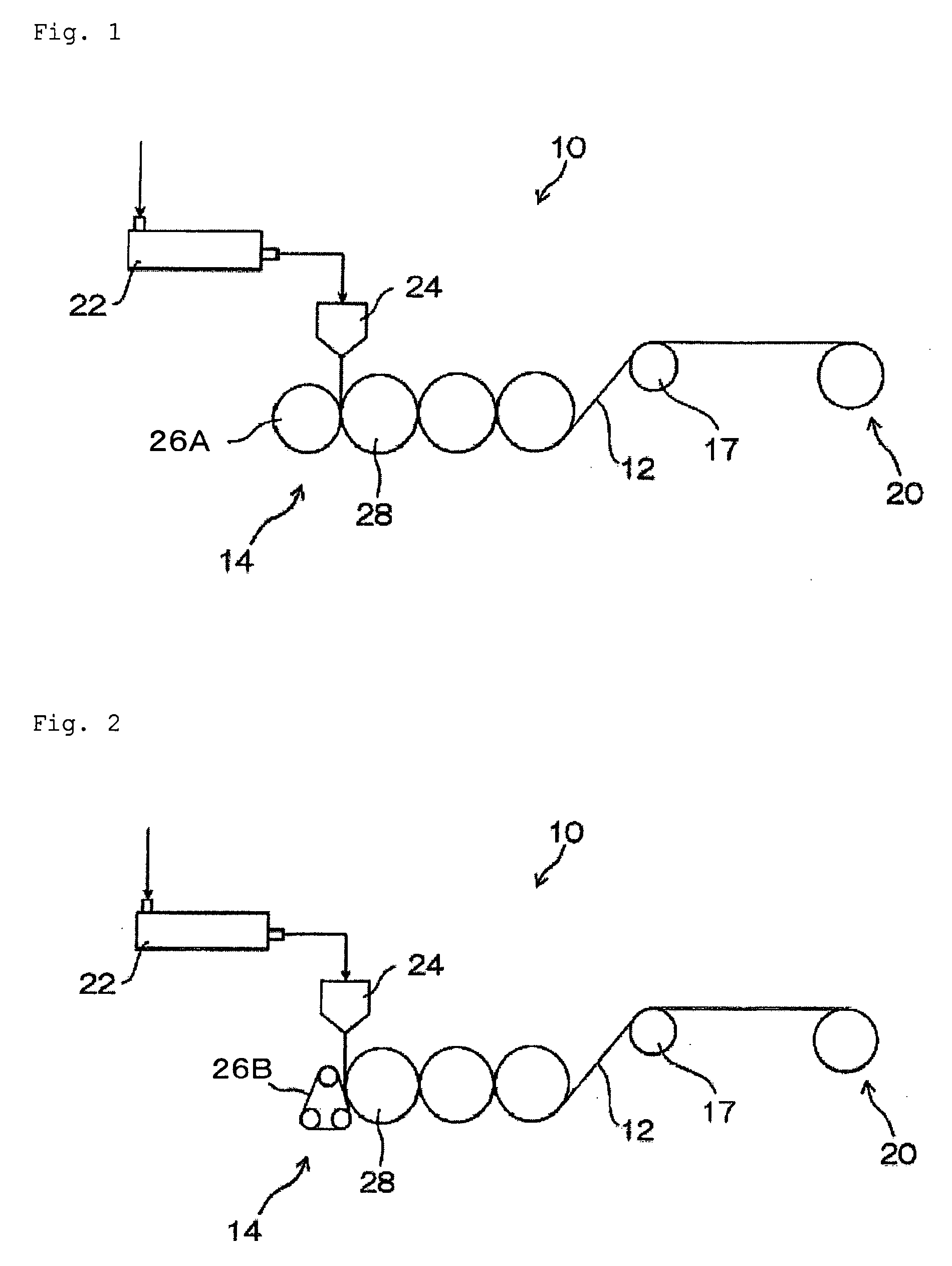
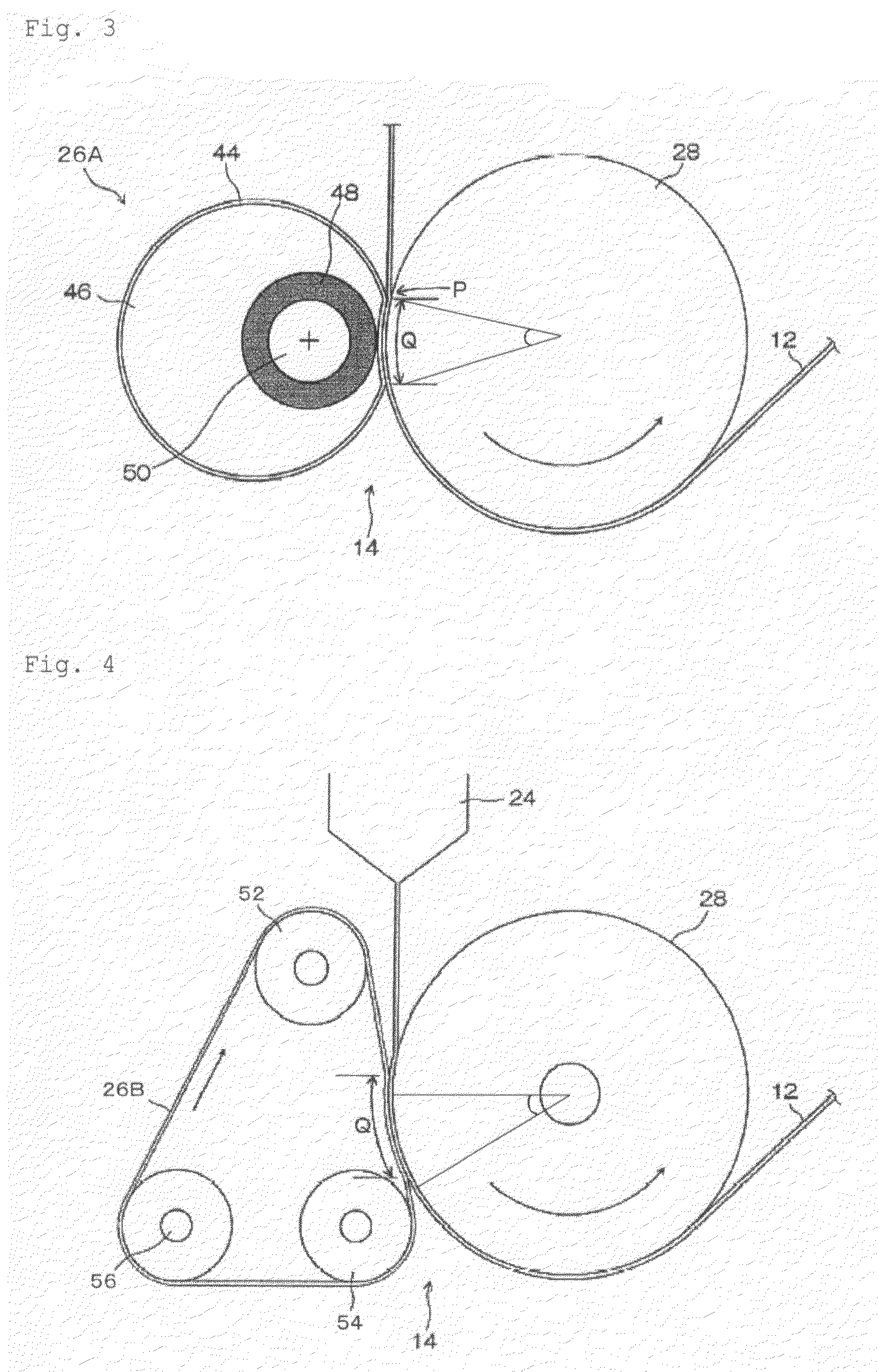
[0060]In the method for producing a thermoplastic film of the invention, the difference between the surface temperature (Tt) of the metallic presser such as a metallic elastic touch roll or a metallic belt used and the surface temperature (T1) of the metallic casting roll for cooling is designed to satisfy the following formula (1), and therefore, when the filmy thermoplastic resin melt is led to pass between the two under pressure, the filmy resin melt may be smoothly led to the casting roll for cooling side, which is therefore extremely effective for canceling the sticking traces on the film and for improving the film surface smoothness. In addition, the film thickness fluctuation, the die streaks and the lateral unevenness owing to the roll driving fluctuation may be greatly reduced. Further, since the touch temperature is controlled within the range of the formula (1), the filmy resin melt hardly sticks to the pressing surface of the metallic presser (the touch surface of the touch roll), and in addition, it also hardly sticks to the roll surface of the casting roll for cooling, and therefore the thermoplastic film may be stably produced in a well-balanced condition.
[0061]When “T1−Tt” in formula (1) is lower than 0.5° C., then the filmy resin melt may stick to the metallic presser such as the metallic elastic touch roll or the metallic belt, and the formed film may have sticking traces and its surface smoothness may worsen. On the other hand, when it is higher than 20° C., then the filmy resin melt may excessively stick to the chill roll surface, and therefore lateral unevenness may occur on the formed film. In addition, when it is higher than 20° C., then there may occur a temperature difference between the two surfaces of the filmy resin melt being led to run between the rolls, and therefore the surface smoothness may differ and uneven between the two surfaces of the formed film. When the above-mentioned condition that “T1−Tt” is from 0.5° C. to 20° C. is satisfied, then it is good with no problem, but preferably it is from 1° C. to 15° C., more preferably from 2° C. to 10° C.
[00

Problems solved by technology

However, it is still impossible to completely prevent the release of organic solvents, and further improvements are required.
However, even though the optical properties of the film are satisfactory in some degree, the surface smoothness thereof in its formation is insufficient, or the thickness accuracy may fluctuate or there may occur a difference in the surface smoothness between the two surfaces of the film owing to the unevenness of the temperature change in the film, and further, there may occur die streaks and lateral unevenness; and for these reasons, it has heretofore been extremely difficult to obtain a film that is excellent both in its optical properties and in its physical properties as a protective film suitable for polarizing plates.
In case where the thickness accuracy and the surface smoothness of a film are unsatisfacto

Method used


Image

  • Thermoplastic film and method of producing the same, polarizing plate, optical compensation film, antireflection film and liquid-crystal display device
  • Thermoplastic film and method of producing the same, polarizing plate, optical compensation film, antireflection film and liquid-crystal display device
  • Thermoplastic film and method of producing the same, polarizing plate, optical compensation film, antireflection film and liquid-crystal display device

Examples


production example 1

[0414]Production of Cellulose Acetate Propionate (CAP1):

[0415]80 parts by mass of cellulose (linter) and 33 parts by mass of acetic acid were put into a reactor equipped with a stirrer and a condenser, and processed at 60° C. for 4 hours to activate the cellulose. 33 parts by mass of acetic anhydride, 518 parts by mass of propionic acid, 536 parts by mass of propionic anhydride and 4 parts by mass of sulfuric acid were mixed and cooled to −20° C., and added to the reactor.

[0416]This was esterified at a maximum reaction temperature of 35° C., and the time at which the viscosity of the reaction liquid reached 840 cP (0.84 Pa·s) was the end point of the reaction. The system was so controlled that the temperature of the reaction mixture at the end point could be 15° C. A mixture of 133 parts by mass of water and 133 parts by mass of acetic acid was cooled to −5° C. to prepare a reaction stopper, and this was added to the reactor so that the temperature of the reaction mixture could not ...

production example 2

[0419]Production of Cellulose Acetate Butyrate (CAB1):

[0420]200 parts by mass of cellulose (wood pulp) and 100 parts by mass of acetic acid were put into a reactor equipped with a stirrer and a condenser, and processed at 60° C. for 4 hours to activate the cellulose. 161 parts by mass of acetic acid, 449 parts by mass of acetic anhydride, 742 parts by mass of butyric acid, 1349 parts by mass of butyric anhydride and 14 parts by mass of sulfuric acid were mixed and cooled to −20° C., and added to the reactor.

[0421]This was esterified at a maximum reaction temperature of 30° C., and the time at which the viscosity of the reaction liquid reached 1050 cP (1.05 Pa·s) was the end point of the reaction. The system was so controlled that the temperature of the reaction mixture at the end point could be 10° C. A mixture of 297 parts by mass of water and 558 parts by mass of acetic acid was cooled to −5° C. to prepare a reaction stopper, and this was added to the reactor so that the temperatu...

example 1

Formation of Unstretched Thermoplastic Film 1:

(1) Additives to Cellulose Acylate:

[0424]The following additive composition was used as in Table 1 below. The amount of each additive is in terms of part by mass of the additive relative to 100 parts by mass of the resin to which it is added.

Composition 1Stabilizer: Sumilizer GP (by Sumitomo Chemical)0.2parts by massStabilizer: Adekastab AO-80 (by Asahi Denka Kogyo)0.15parts by massStabilizer: Adekastab 2112 (by Asahi Denka Kogyo)0.15parts by massUV absorbent: Adekastab LA-31 (by Asahi Denka Kogyo)1.1parts by massFine particles: silica particles having a mean primary particle0.05parts by masssize of 1.2 μm (the proportion by mass of 0.9 to 1.5 μm particlesis at least 95%; and that of larger particles than 1.5 μmparticles is at most 1.0%)Composition 2Stabilizer: Adekastab AO-60 (by Asahi Denka Kogyo)0.2parts by massStabilizer: Adekastab PEP36 (by Asahi Denka Kogyo)0.2parts by massStabilizer: Adekastab O-180A (by Asahi Denka Kogyo)1part by...


PUM

PropertyMeasurementUnit
Temperatureaaaaaaaaaa

Abstract

A method for producing a thermoplastic film, comprising cooling and solidifying a filmy thermoplastic melt resin, by holding it between a metallic presser and a metallic casting roll for cooling; wherein the temperature of the filmy thermoplastic resin just before being held between the metallic presser and the casting roll for cooling is from Tg+20° C. to Tg+90° C. and a difference between a surface temperature (Tt) of the metallic presser and a surface temperature (T1) of the casting roll for cooling satisfies the formula (1) and a contact length Q satisfies the following formula (2)
0.5° C.≦T1−Tt≦20° C.   (1)
0.1 cm≦Q≦8 cm   (2)
The method provides a thermoplastic film having high thickness accuracy and surface smoothness.

Description

FIELD OF THE INVENTION[0001]The present invention relates to a thermoplastic film and a method for producing it, in particular to a thermoplastic film having a quality favorable for liquid-crystal display devices and a method for producing it, and also relates to a polarizing plate, an optical compensation film, an antireflection film and a liquid-crystal display device comprising it.BACKGROUND OF THE INVENTION[0002]Heretofore, in producing thermoplastic films such as cellulose acylate films for use in liquid-crystal image display devices, a solution-casting method has been principally carried out, which comprises dissolving cellulose acylate in a chlorine-containing organic solvent such as dichloromethane, casting it on a substrate, and drying it to form a film. Of chlorine-containing organic solvents, dichloromethane is favorably used since it is a good solvent for cellulose acylate and since it has advantages in that its boiling point is low (about 40° C.) and it may be readily v...

Claims


Application Information

Patent Timeline
IPC IPC(8): C09K19/00B29C48/08B29C48/305B29C48/91
CPCB29C47/0021Y10T428/1041B29C47/8855B29C55/06B29C55/12B29C55/16B29K2001/00B29K2001/12B29K2023/38B29K2995/0034C08J5/18C08J2301/02C08L1/10G02B5/30B29C47/8845Y02P20/582B29C48/08B29C48/91B29C48/914B29C48/915B29C48/9155C09K2323/031
Inventor SHI, ZEMINONO, KAZUHIRO
Owner FUJIFILM CORP
Why Eureka
Try Eureka