Liquid crystal display device

a liquid crystal display and display device technology, applied in the direction of instruments, light sources, electrical appliances, etc., can solve the problems of the inability to make corrections to one particular color alone, and the inability to adjust the light intensity of leds, etc., to achieve suitable brightness and large temperature-dependent variation

Inactive Publication Date: 2007-05-31
SHARP KK
View PDF6 Cites 12 Cited by
  • Summary
  • Abstract
  • Description
  • Claims
  • Application Information

AI Technical Summary

Benefits of technology

[0014] In view of the above problem, the present invention is aimed at providing a liquid crystal display device capable of achieving improved color reproducibility even if plural kinds of light sources are used as the backlight.
[0020] In accordance with the first aspect of the present invention, lighting control can be performed by applying a voltage to the first light source with a duty ratio of 100% until the temperature inside the liquid crystal display device becomes equal to or greater than a predetermined temperature. For example, when cathode fluorescent lamps are used as the first light source, it is possible to enhance the brightness by setting the duty ratio to be 100% even though the brightness of cathode fluorescent lamps is low when it is started up (during low temperatures). As a result it is possible to perform the whole display of the liquid crystal display device in a well-balanced condition.
[0021] In accordance with the second aspect of the present invention, when the detected temperature has become equal to or higher than the previously set first temperature, lighting control will be performed in the set duty ratio. Accordingly, when the detected temperature becomes equal to or higher than the first temperature, the brightness is adjusted into that designated by the user, so that the power consumption, for example can be reduced.
[0023] In accordance with the fourth aspect of the present invention, the first light source is composed of cathode fluorescent lamps (CFLs), and the second light source is composed of light emitting diodes (LEDs). Accordingly, even in a liquid crystal display device using a hybrid backlight made up of cathode fluorescent lamps which present a large temperature-dependent variation and light emitting diodes which are prone to be affected by change in voltage, it is possible to secure suitable brightness.
[0024] In accordance with the fifth aspect of the present invention, lighting control is performed by detecting the RGB values of light emitted from the backlight and determining the duty ratio for the second light source in accordance with the detected RGB values. Accordingly, it is possible to set up suitable white balance in the backlight.

Problems solved by technology

However, if the power (brightness) of CFL is increased, all the colors are uniformly raised in brightness, so it has been impossible to make correction to one particular color alone.
However, the above hybrid backlight configuration entails the following problem.
In this case, if current IF is set to a markedly low value, there occurs the problem that the LEDs will not light correctly because of an insufficiency of the current supplied to the LEDs.
However, it is only possible to extract sufficient LED illumination characteristics when a forward voltage of about 1.6 to 1.8 V is applied to each LED element, so that there is a certain limit that the light intensity of LEDs can be adjusted, hence resulting in inability of correct illumination.
For example, there have occurred the problems that LEDs cannot be totally turned on and that LEDs are turned on but flickering.
However, if the voltage V is varied to 11 [V] in order to reduce the LED brightness, the current IF is sharply reduced to (11−9.6) / 430≈3 [mA], which cannot turn on the LEDs correctly.
In this way, when a backlight with a series of LEDs is used, there occurs the inherent problem that it is impossible to perform lighting control by voltage control only.

Method used


Image

  • Liquid crystal display device
  • Liquid crystal display device
  • Liquid crystal display device

Examples


Embodiment Construction

[0033] Now, the embodiment in which a liquid crystal display device of the present invention is applied to an LCD television will be described with reference to the drawings.

[Configuration]

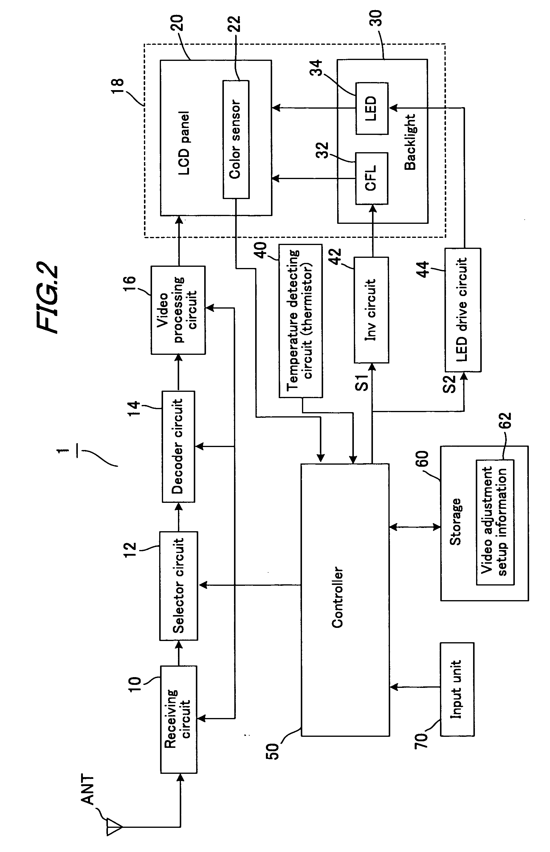
[0034]FIG. 2 is a block diagram showing a configuration of an LCD television 1. LCD television 1 includes a receiving circuit 10, a selector circuit 12, a decoder circuit 14, a video processing circuit 16, an LCD 18, a temperature detecting circuit (thermistor) 40, an inverter (INV) circuit 42, an LED drive circuit 44, a controller 50, a storage 60 and an input unit 70, and has an external antenna ANT connected thereto.

[0035] LCD 18 is composed of an LCD panel 20 and a backlight 30, which are housed integrally. LCD 18 further includes a color sensor 22 that detects RGB values based on the light irradiated by the backlight for LCD panel 20. In addition, backlight 30 includes as its light sources a CFL module 32 and a LED module 34.

[0036] Receiving circuit 10 extracts broadcast signals from the ...


PUM


Abstract

When the temperature value detected by a temperature detecting circuit is lower than a previously designated set temperature value, cathode fluorescent lamps (CFLs) are operated to illuminate with a duty ratio of 100% so as to enhance the brightness. When the detected temperature value has become equal to or higher than the previously designated set temperature value, CFLs are operated to illuminate by changing the duty ratio into a user set value.

Description

[0001] This Nonprovisional application claims priority under 35 U.S.C. §119(a) on Patent Application No. 2005-343757 filed in Japan on 29 Nov. 2005, the entire contents of which are hereby incorporated by reference. BACKGROUND OF THE INVENTION [0002] 1. Field of the Invention [0003] The present invention relates to a liquid crystal display device. [0004] 2. Description of the Prior Art [0005] Conventionally, one of the display devices for displaying images, videos and others, liquid crystal display devices (LCD) that make use of liquid crystal have been known. LCDs have been mostly utilized as display devices for computers, cellular phones, television sets and the like. In a liquid crystal display device, a special liquid is sandwiched and sealed between two glass plates, and when an electric field is applied across the liquid, a change in the orientation of liquid crystal molecules occurs so that the light transmittance of the liquid varies to thereby display an image. In this proc...

Claims


Application Information

Patent Timeline
Patent Type & Authority Applications(United States)
IPC IPC(8): H05B39/04
CPCG09G3/3413G09G2320/041G09G2330/026G09G2360/145
Inventor MORIYASU, MITSUHIROCHIKAZAWA, HIDEYUKI
Owner SHARP KK
Why Eureka
Try Eureka