Gear apparatus

a gearbox and gear technology, applied in the direction of gearing elements, toothed gearings, gearings, etc., can solve the problems of extreme torque applied to teeth, large load on gears, and durability problems, and achieve the effects of high durability, reliable and easy assembly, and good balan

Inactive Publication Date: 2003-02-20
SEIKO EPSON CORP
View PDF0 Cites 10 Cited by
  • Summary
  • Abstract
  • Description
  • Claims
  • Application Information

AI Technical Summary

Benefits of technology

0009] With the present invention it is possible to configure a gear train that has high durability despite miniaturization and can be reliably and easily assembled because the first gear parts of the n planetary gears between the sun gear and fixed internal tooth gear can be assembled meshing at equal intervals around the axis, the second gear parts of the n planetary gears can be reliably assembled meshed in the same way with the movable internal tooth gear, and a very well balanced condition can be achieved in the planetary gear mechanism even though the gear train is small (even if the gear module of the gear forms is small), because the phases of the gear forms at equidistant points dividing the circumference of each gear in n equal parts are mutually matched as a result of the tooth counts e, z.sub.1, z.sub.2, I.sub.1 and I.sub.2 of the sun gear, first gear parts and second gear parts of the planetary gears, fixed internal tooth gear and movable internal tooth gear all being a multiple of n (where n is a natural number of 2 or more). Furthermore, because there is only the constraint that the tooth count of each gear be a multiple of n, and the tooth count of the first gear part and the tooth count of the second gear part of the planetary gears are not required to be the same, the tooth count combinations can be set more freely and a high gear reduction ratio can be easily achieved. Moreover, because there are more than two planetary gears, the load on the gears is less compared with when only one planetary gear is used.
0010] In the present invention n is preferably 2 or 3. Because the section area of the support stud part projecting in the axial direction of the sun gear can be assured in the carrier (or holder) axially supporting the planetary gears as a result of the number of planetary gears being 2 or 3, rigidity loss in the carrier can be suppressed even when the gear train is miniaturized, and the rotational axis of the planetary gear can be reliably supported.
0011] Problems also do not occur in the present invention even when the gear reduction ratio is 200 or greater when the sun gear is the input and the movable internal tooth gear is the output. When the gear reduction ratio is 300 or greater, the number of planetary gears is normally reduced or it is difficult to achieve a configuration enabling the gears to be assembled with the above-described prior art, but with a gear train having the configuration of the present invention

Problems solved by technology

As a result, the sun gear and planetary gear always mesh at only one place (one tooth each), the torque applied to the teeth becomes extreme and the load on the gears becomes great, leading to problems with

Method used


Image

  • Gear apparatus
  • Gear apparatus
  • Gear apparatus

Examples


Embodiment Construction

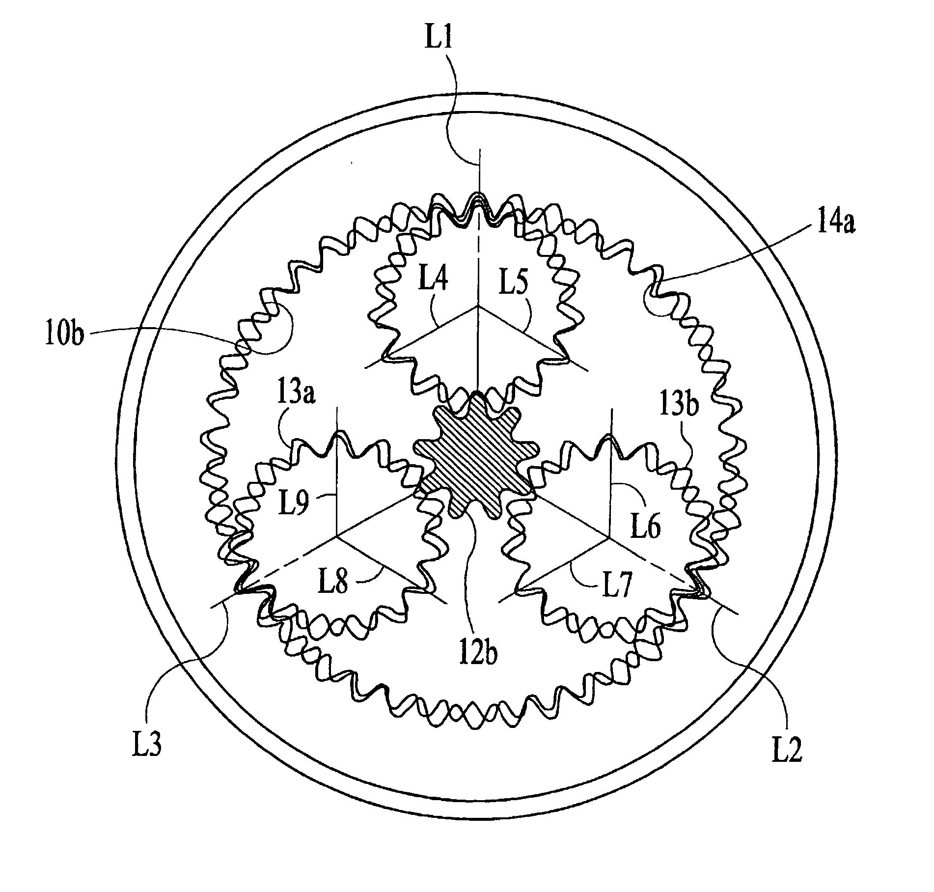
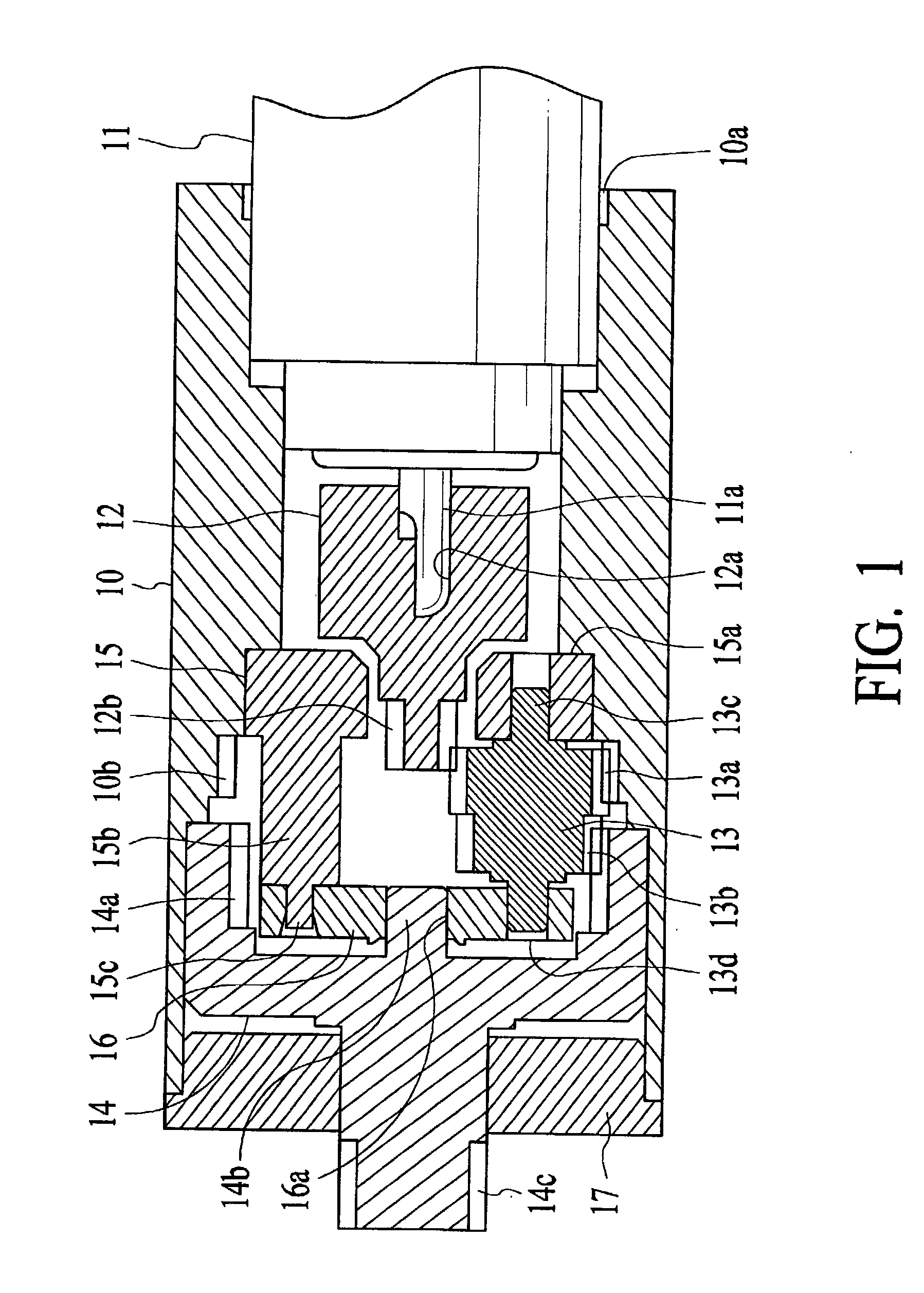
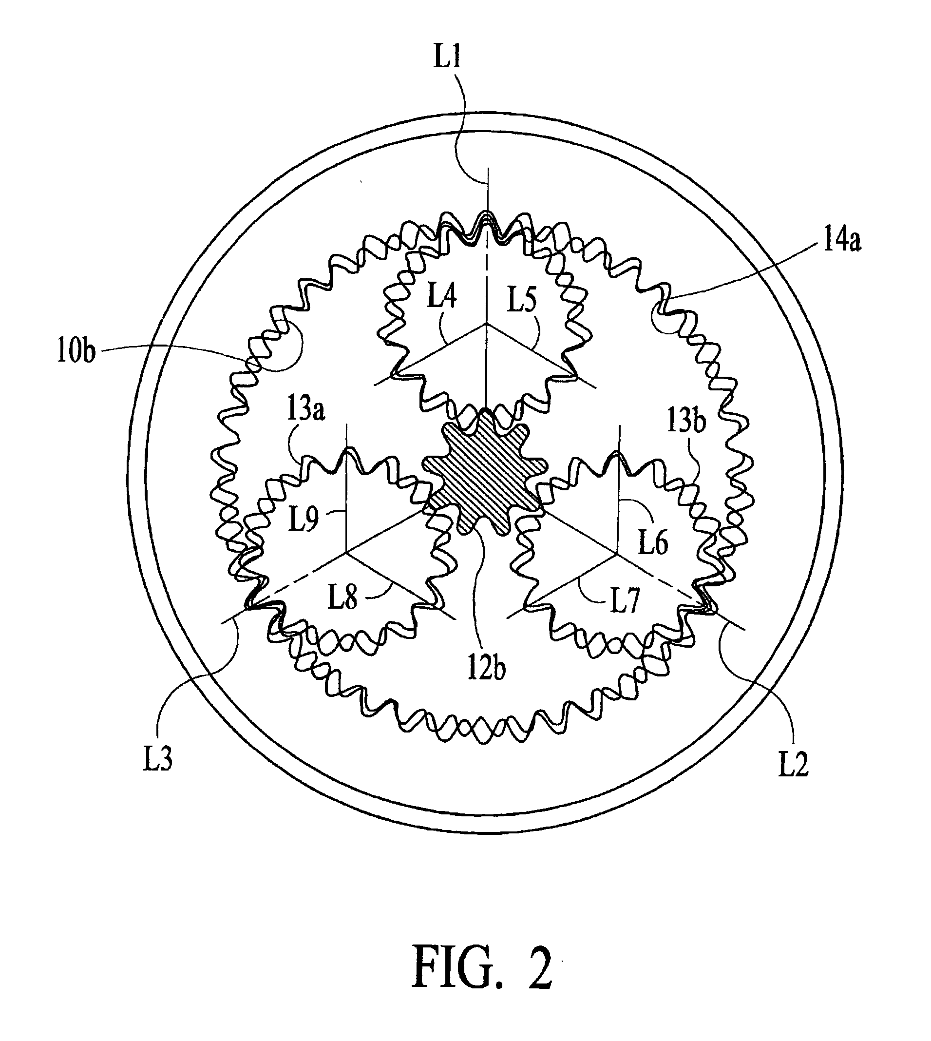
[0019] A preferred embodiment of a gear train according to the present invention is described next below with reference to the accompanying figures. FIG. 1 is a longitudinal section view showing the internal structure of this preferred embodiment. A small motor 11 is fit into an opening at one end (the right end as seen in the figure) of a cylindrical housing 10 formed by injection molding, for example, and the body of this small motor 11 is fixed by adhesion to this housing 10 by flowing an adhesive into adhesive holder 10a. The output shaft 11a of the small motor 10 is fit into center hole 12a of input member 12. This input member 12 is also a resin molding, for example, formed by injection molding, for example. Sun gear 12b is integrally formed to an end of input member 12.

[0020] The sun gear 12b mates with planetary gear 13. The planetary gear 13 has a first gear part 13a meshing with sun gear 12b, a second gear part 13b formed coaxially to this first gear part 13a, supported ax...


PUM


Abstract

Having a sun gear with a tooth count e, n (where n is a natural number of 2 or more) planetary gears having a first gear part with a tooth count z.sub.1 meshing with the sun gear and a second gear part with a tooth count z.sub.2, a fixed internal tooth gear with a tooth count I.sub.1 meshing with the first gear part of the planetary gear, and a movable internal tooth gear with a tooth count I.sub.2 meshing with the second gear part of the planetary gear, tooth counts e, z.sub.1, z.sub.2, I.sub.1 and I.sub.2 are all a multiple of n. Even if the gear form of each gear has a small module, a planetary gear train mechanism can be configured without causing operating or assembly problems, and it is possible to provide a gear train that can be miniaturized more than conventionally and still have a sufficient gear reduction ratio.

Description

TECHNICAL FIELD[0001] The present invention relates to a gear train, and relates particularly to the configuration of a gear train having a planetary gear train mechanism suitable for configuring a small speed reducer.PRIOR ART[0002] Speed reducers using a planetary gear train mechanism are widely used in the drive mechanism of various types of mechanical devices because they are generally compact and achieve a high gear reduction ratio. An example of this type of speed reducing apparatus is the compact speed reducer disclosed in Japanese Patent Laid-Open Publication (kokai) H2-31047. This compact speed reducer has a sun gear, a planetary gear meshing with the sun gear, a fixed internal tooth gear meshing with a first gear part of the planetary gear, and a movable internal tooth gear coaxial to the fixed internal tooth gear and meshing with a second gear part of the planetary gear. The first gear part meshing with the fixed internal tooth gear and the second gear part meshing with t...

Claims


Application Information

Patent Timeline
IPC IPC(8): F16H1/46
CPCF16H1/46F16H2001/2881Y10S475/904
Inventor USHIKOSHI, KENICHI
Owner SEIKO EPSON CORP
Why Eureka
Try Eureka