Pitch shifting apparatus

a technology of shifting apparatus and pitch, which is applied in the field of pitch shifting apparatus, can solve the problems of unnatural sound of pitch shifting sound,

Inactive Publication Date: 2007-12-06
YAMAHA CORP
View PDF3 Cites 14 Cited by
  • Summary
  • Abstract
  • Description
  • Claims
  • Application Information

AI Technical Summary

Benefits of technology

[0005] Therefore, one of the objects of the present invention is to provide a pitch shifting apparatus which substantially compresses or expands amplitude spectra at

Problems solved by technology

As a consequence, the problem arises that the p

Method used


Image

  • Pitch shifting apparatus
  • Pitch shifting apparatus
  • Pitch shifting apparatus

Examples


Embodiment Construction

[0053] Next, a pitch shifting apparatus according to an embodiment of the present invention will be described referring to the drawings.

(Constitution)

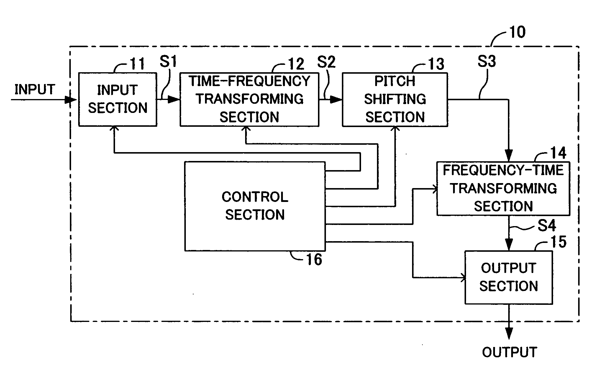
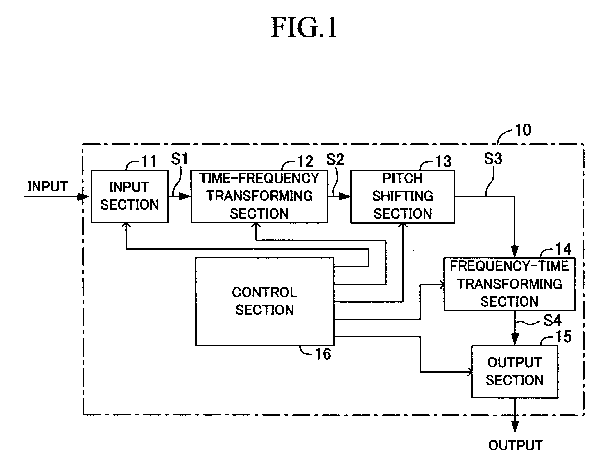
[0054] As shown in FIG. 1, the present pitch shifting apparatus 10 includes an input section 11, a time-frequency transforming section 12, a pitch shifting section (pitch processing section) 13, a frequency-time transforming section 14, an output section 15, and a control section 16. In a practical sense, functions of these sections are realized (performed) by an execution of given programs executed by a CPU (not shown) of the pitch shifting apparatus 10 which is a computer including the control section 16.

[0055] The input section 11, which includes an A / D converter which converts an input analog signal into a digital signal and outputs it, is configured to convert an input analog sound signal into a digital signal (data) S1. The data thus obtained is sound data represented in the time domain (time domain representation sound data)...


PUM


Abstract

A pitch shifting apparatus detects peak spectra P1 and P2 from amplitude spectra of inputs sound. The pitch shifting apparatus compresses or expands an amplitude spectrum distribution AM1 in a first frequency region A1 including a first frequency f1 of the peak spectrum P1 using a pitch shift ratio which keeps its shape to obtain an amplitude spectrum distribution AM10 for a pitch-shifted first frequency region A10. The pitch shifting apparatus similarly compresses or expands an amplitude spectrum distribution AM2 adjacent to the peak spectrum P2 to obtain an amplitude spectrum distribution AM20. The pitch shifting apparatus performs pitch shifting by compressing or expanding amplitude spectra in an intermediate frequency region A3 between the peak spectra P1 and P2 at a given pitch shift ratio in response to the each amplitude spectrum.

Description

CROSS-REFERENCE TO RELATED APPLICATION [0001] This application is a continuation of co-pending International Application No. PCT / JP2005 / 020156 filed on Oct. 27, 2005 and published under PCT Article 21(2) on May 4, 2006 as International Publication No. WO 2006 / 046761, the contents of which are incorporated herein by reference.TECHNICAL FIELD [0002] The present invention relates to a pitch shifting apparatus which shifts (or alters) a pitch of sound data. BACKGROUND ART [0003] Various pitch shifting apparatuses which alter (or shift) a pitch of sound data, such as voice data and musical sound data, have been known. One of these pitch shifting apparatuses transforms given sound data from data represented in the time domain (time domain representation) into data represented in the frequency domain (frequency domain representation), identifies a frequency region which includes a peak spectrum of an amplitude spectrum based on the transformed sound data and shifts only amplitude spectra w...

Claims


Application Information

Patent Timeline
IPC IPC(8): G10L11/04G10L21/013G10L21/034G10L25/90
CPCG10H7/002G10H2210/331G10H2250/235G10L21/04G10L21/003G10L21/013G10H2250/621
Inventor FUJISHIMA, TAKUYABONADA, JORDI
Owner YAMAHA CORP
Why Eureka
Try Eureka