Selective plating system

Inactive Publication Date: 2007-12-13
SIFCO SELECTIVE PLATING
View PDF11 Cites 10 Cited by
  • Summary
  • Abstract
  • Description
  • Claims
  • Application Information

AI Technical Summary

Benefits of technology

[0008] An advantage of the present invention is a method and apparatus for selectively plating sections of a work piece.
[0009] An advantage of the present invention is a system having a plating fixture for encapsulating the sections of the work piece to be plated.
[0010] An advantage of the present invention is a system as described above wherein the encapsulating fixture includes means to facilitate cleaning of the areas to be plated.
[0011] Another advantage of the present invention

Problems solved by technology

Such a plating process requires large facilities, handling equipment and plating tanks.
With such large handling equipment and tanks

Method used


Image

  • Selective plating system
  • Selective plating system
  • Selective plating system

Examples


Example

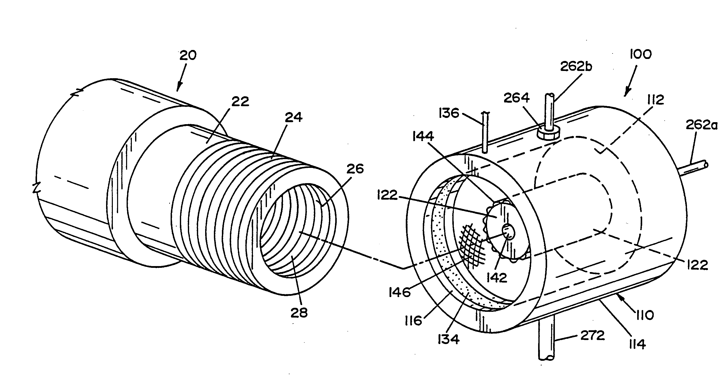
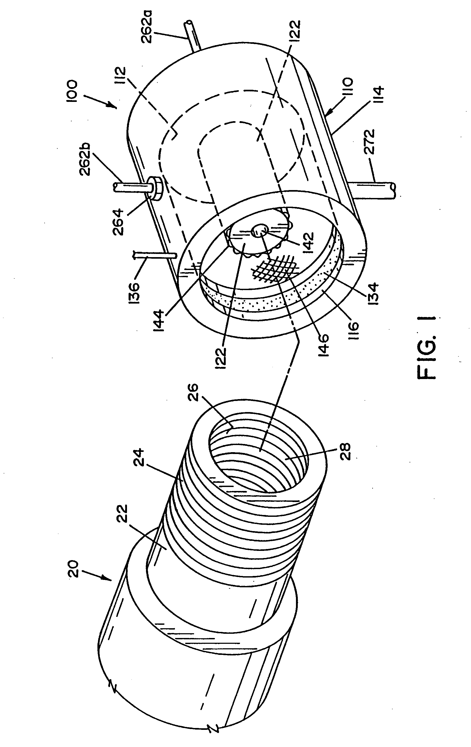
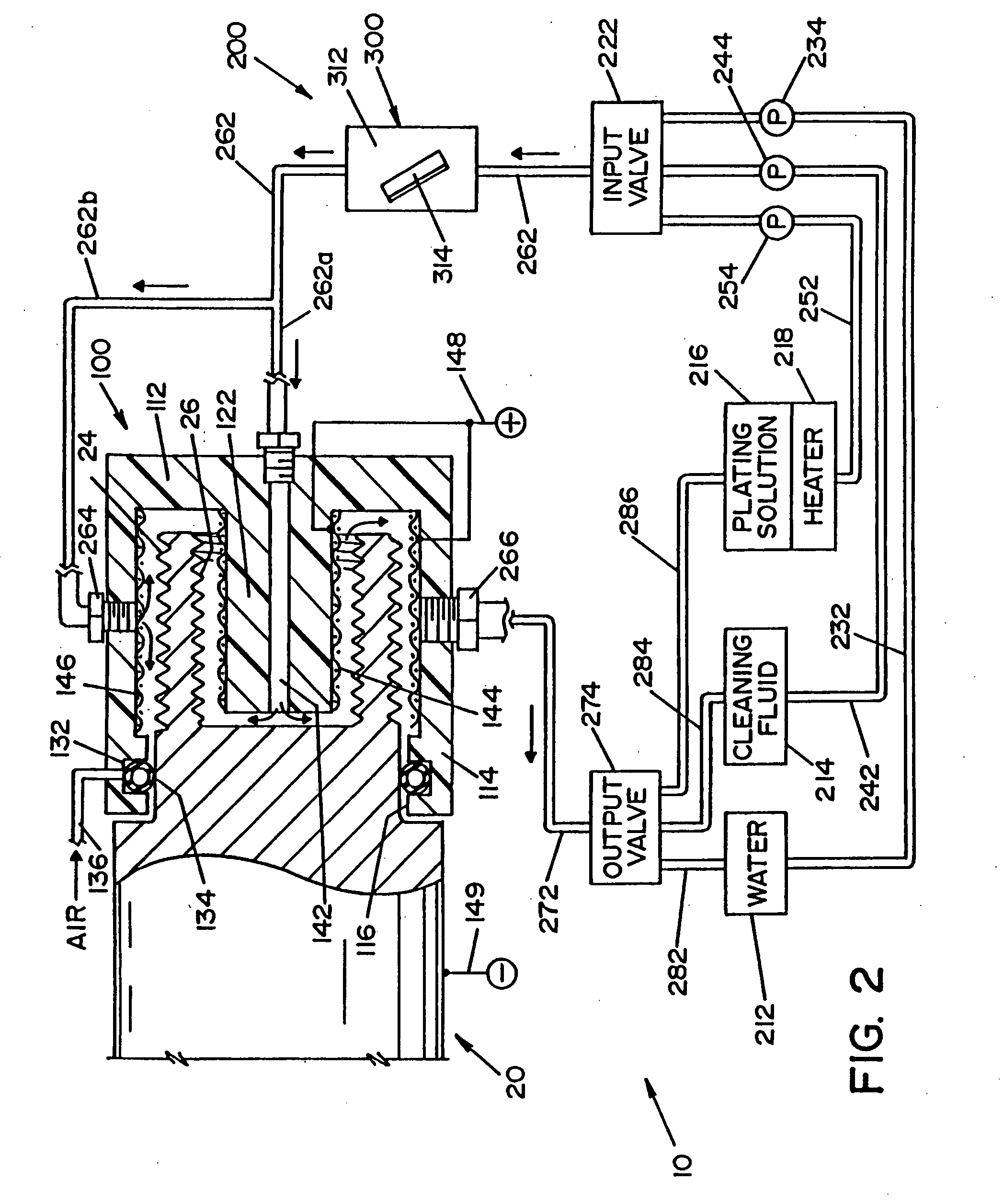
[0022] Referring now to the drawings wherein the showings are for the purpose of illustrating a preferred embodiment of the invention only, and not for the purpose of limiting same, the drawings show a plating system 10 for selectively plating select areas of a large work piece 20. The present invention is particularly applicable to plating screw threads on the ends of a long shaft, such as, by way of example and not limitation, the internal and external threads on the ends of a jet engine shaft, and shall be described with particular reference thereto. It shall be understood, however, that the present invention finds advantageous application in plating other types of work pieces. System 10 is generally comprised of a plating fixture 100, a fluid circulation system 200 and a test strip container 300.

[0023] Referring now to FIG. 1, work piece 20 is a shaft having a tubular end portion 22. Tubular end portion 22 has a threaded outer section 24 and a threaded inner section 26. Tubular...


PUM

PropertyMeasurementUnit
Temperatureaaaaaaaaaa
Flow rateaaaaaaaaaa
Distanceaaaaaaaaaa

Abstract

There is provided an apparatus for plating a portion of a work piece. The apparatus comprises a fixture having a cavity formed therein. The cavity is dimensioned to receive the portion of the work piece. An attaching means is provided for attaching the fixture to the work piece whereby a sealed chamber is formed between the fixture and the work piece. An inlet port in the fixture fluidly communicates with the sealed chamber. An outlet port in the fixture fluidly communicates with the sealed chamber. A circulation system fluidly connects to the inlet port and the outlet port and includes a source of a plating solution. The circulation system is operable to circulate a plating solution through the sealed chamber.

Description

FIELD OF THE INVENTION [0001] The present invention relates generally to plating, and more particularly, to selective plating of intricate surfaces on a work piece. BACKGROUND OF THE INVENTION [0002] The present invention relates to a method and apparatus for selectively plating intricate surfaces on a work piece. By way of example and not limitation, the present invention finds advantageous application in selectively plating threaded surfaces on the end of a shaft, such as threads on the end shaft for a jet engine. Heretofore, it was known to plate nickel onto the threaded ends of a jet engine shaft by masking certain portions of the shaft and suspending the shaft over a large plating tank, and then dipping the end of the shaft in an electroless nickel solution. Such a plating process requires large facilities, handling equipment and plating tanks. With such large handling equipment and tanks, it is difficult to accurately control the plating conditions and the properties of the me...

Claims


Application Information

Patent Timeline
IPC IPC(8): C25D7/00
CPCC25D5/02C25D5/08C25D21/02C25D21/12C25D17/004C25D7/04C23C18/1603C23C18/1605C23C18/1619
Inventor PIPER, GREGORY L.WANG, JUE
Owner SIFCO SELECTIVE PLATING
Why Eureka
Try Eureka