
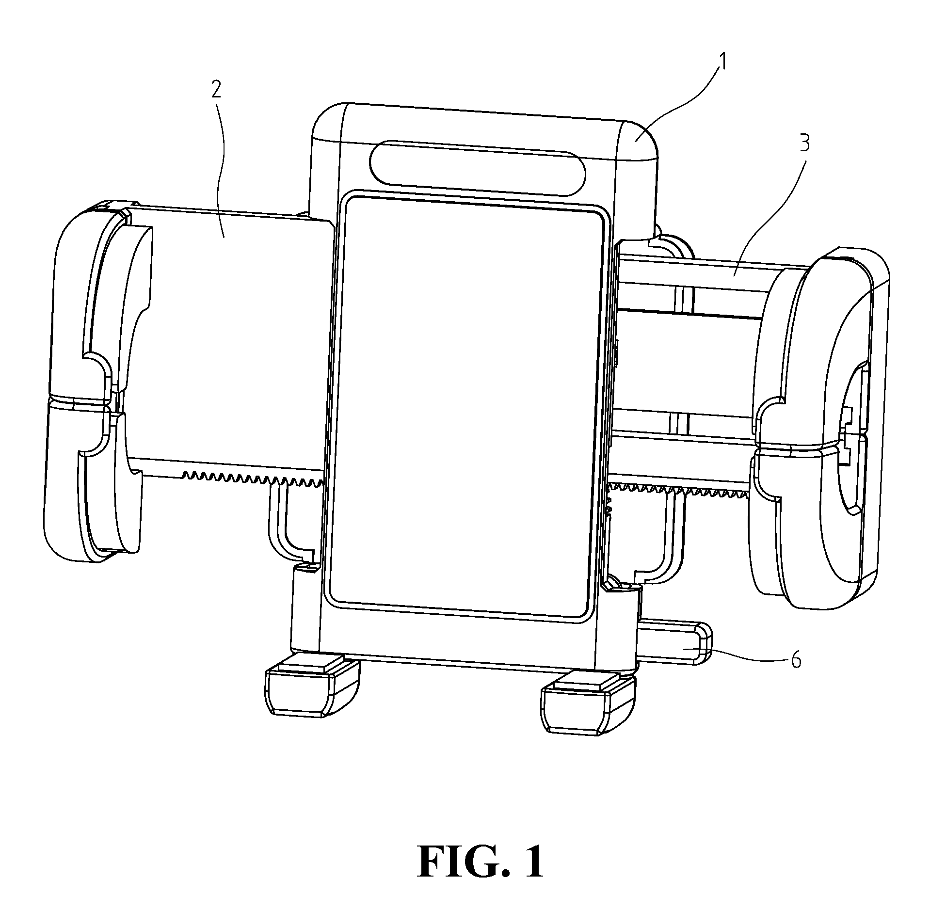
Holding Device For Electronic Apparatus

a technology for holding devices and electronic devices, which is applied in the direction of machine supports, furniture parts, other domestic objects, etc., can solve the problems of hampered automatic slide-open movement of clamping pieces

Active Publication Date: 2007-12-13
FAN EAGLE
View PDF5 Cites 102 Cited by
  • Summary
  • Abstract
  • Description
  • Claims
  • Application Information

AI Technical Summary

Benefits of technology

[0006]The present invention has been made to overcome the above-mentioned drawbacks of conventional holding device for electronic apparatus. The primary object of the present invention is to provide a holding device with a manual gradual open mode. By using manual units, the clamping pieces can be opened with an appropriate width as to release the clamped electronic apparatus so that the electronic apparatus will not fall off the holding seat at the snapping of the clamping pieces and no noise will be generated.
[0008]Yet another object of the present invention is to provide a holding device more suitable for actual use. Although a holding device with large space between the clamping pieces allows the application to a plurality of electronic apparatuses of difference sizes, the use, however, usually uses the holding device to hold a single electronic device at a time, such as a cell phone. Therefore, it is unnecessary to open the clamping pieces as wide as possible to release the clamped electronic apparatus. The present invention provides the adjustment to the widest open position at the initial use and the gradual release of the clamping pieces for convenience, which is suitable for actual use.

Problems solved by technology

The slide-close movement of the clamping pieces is not hampered, while the automatic slide-open movement of the clamping pieces is hampered, which can only be activated by manual unit.

Method used


Image

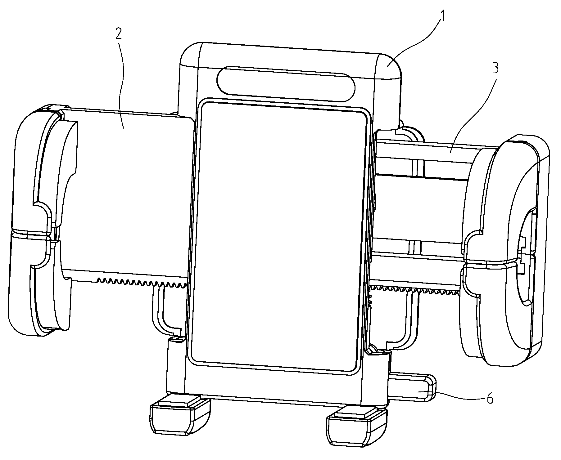
  • Holding Device For Electronic Apparatus
  • Holding Device For Electronic Apparatus
  • Holding Device For Electronic Apparatus

Examples


second embodiment

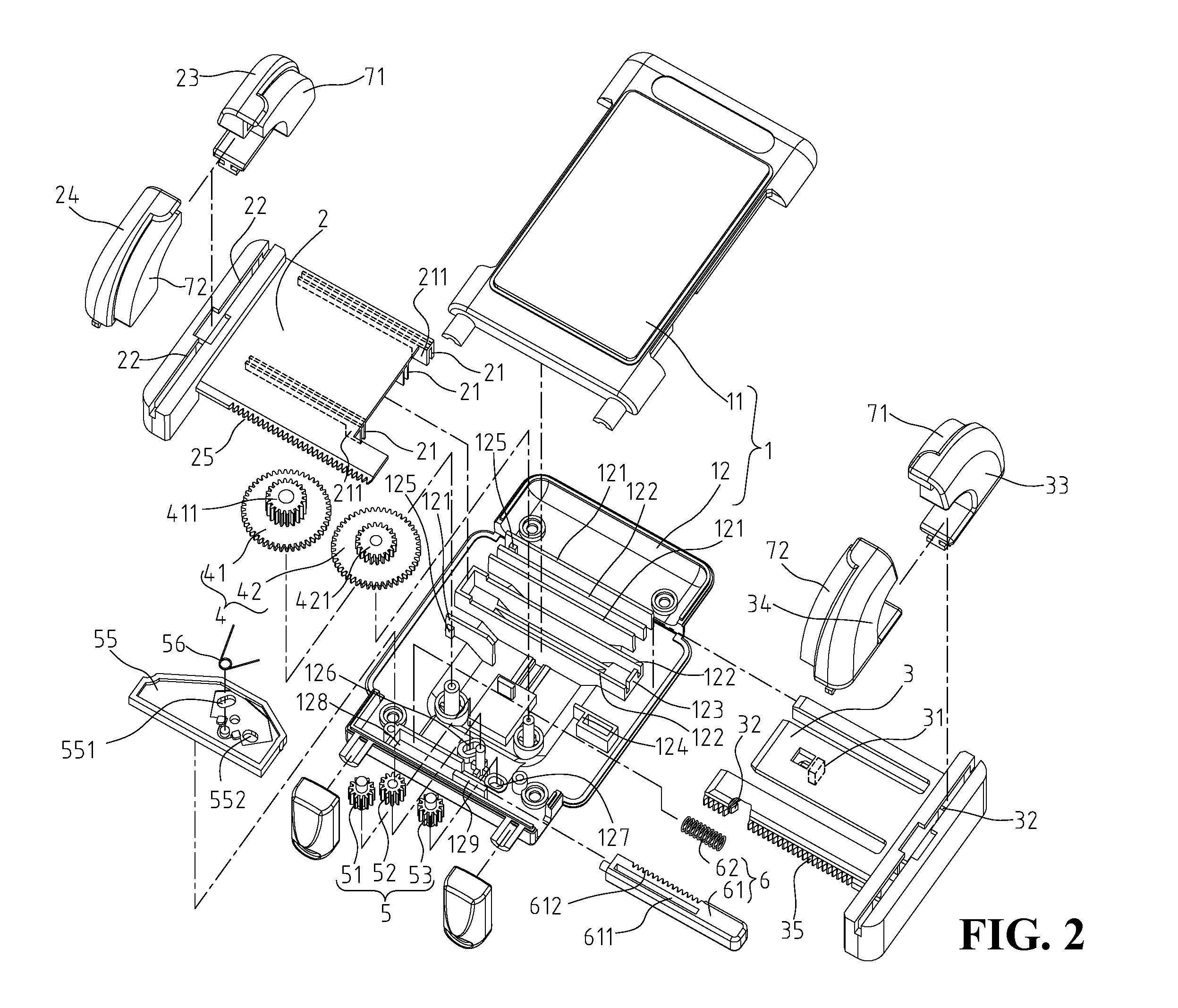
[0034]FIG. 8 shows the present invention. The previous embodiment show synchronous sliding of both clamping pieces. The present embodiment only allows clamping piece 2 to move, while clamping piece 3 is fixed to seat 1. The internal structure include gear set 4, stop unit 5, and manual unit 6. Gear set 4 includes first gear 41 and third gear 43, and third gear 43 is only engaged to first gear 41 and not engaged to any other gears. The purpose is to allow stop unit 5o to reach the self-lock position. In other words, the present invention is also applicable to one-directional clamping.

third embodiment

[0035]FIG. 9 shows the present invention. This embodiment include a different design of a manual unit 7, including a turning wheel 71 partially exposed outside of seat 1, and a co-axial gear 72. Moveable gear 53 of stop unit 5 moves along an arc path, and is engaged to gear 72 of manual unit 7. To open clamping pieces 2, 3, turning wheel 71 is turned counter-clockwise so that gear 72 is engaged to moveable gear 53 for operation. In other words, the manual unit of the present invention is not limited to the operation by push, but can also be operated by turning.

[0036]In summary, the manual gradual opening mode of the holding device of the present invention allows the user to gradually open the clamping pieces after the initial clamping. This provides more convenient, less noisy, and smooth operation. The self-lock feature of the stop unit also effectively holds the clamped apparatus.


PUM


Abstract

A holding device is provided, including a seat affixed with two clamping pieces. At least one of the clamping pieces can slide transversely towards or backwards from the other. Inside the seat, a gear set, a stop unit and a manual unit are included so that clamping pieces can synchronously slide. The slide-close movement of the clamping pieces is not hampered, while the automatic slide-open movement of the clamping pieces is hampered, which can only be activated by manual unit. In addition, a gradual open mode is used for opening the clamping pieces to release the clamped apparatus. The present invention provides a noise-free and convenient operation.

Description

FIELD OF THE INVENTION[0001]The present invention generally relates to a holding device for electronic apparatus, and more specifically to a holding device with a manual gradual open mode, applicable to a plurality of electronic apparatuses.BACKGROUND OF THE INVENTION[0002]A holding device is mainly used in a vehicle for holding an electronic apparatus, such as mobile phone, PDA, and so on. The conventional holding device includes two moveable clamping pieces. The holding device also includes springs to provide the force to move the two moveable clamping pieces transversely to each other. The holding device further includes a set of stop pieces to control and lock the clamping pieces to a certain position so that the electronic apparatuses of different sizes can dock fastened. The holding device also includes a release unit for releasing the stop pieces from the locking position so that the spring will force the moveable clamping pieces and release the electronic apparatus from the ...

Claims


Application Information

Patent Timeline
IPC IPC(8): A47B91/00
CPCB60R11/02B60R11/0241H04M1/04B60R11/0258B60R2011/0071B60R11/0252H04B1/3877
Inventor FAN, EAGLE
Owner FAN EAGLE
Learn More