Capacitive switch of electric/electronic device

a technology of electric/electronic devices and capacitor switches, which is applied in the direction of fixed capacitor details, pulse techniques, instruments, etc., can solve the problems of generating voids between contacts and capacitive sensors, voids may be formed, and capacitive switches may malfunction, so as to achieve the effect of easily removing a plurality of voids

Inactive Publication Date: 2007-12-13
LG ELECTRONICS INC
View PDF17 Cites 21 Cited by
  • Summary
  • Abstract
  • Description
  • Claims
  • Application Information

AI Technical Summary

Benefits of technology

[0010]The present invention provides a capacitive switch of an electric/electronic device which can ea

Problems solved by technology

However, in the case of conventional capacitive switches, voids may be formed when either contacts or capacitive sensors are not uniformly arranged.
In this case, the capacitive switches may malfunction due to the voids.
In other words, if the controller has an uneven surface or the capacitive sensors have different heights, the capacitive sensors may not be properly attached onto the

Method used


Image

  • Capacitive switch of electric/electronic device
  • Capacitive switch of electric/electronic device
  • Capacitive switch of electric/electronic device

Examples


Embodiment Construction

[0030]The present invention will hereinafter be described in detail with reference to the accompanying drawings in which exemplary embodiments of the invention are shown.

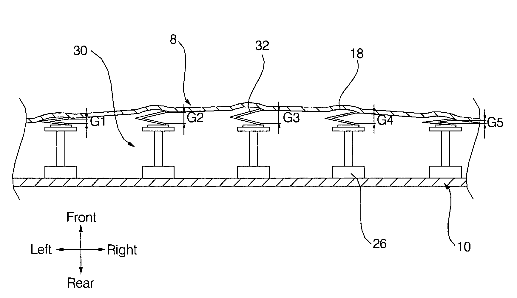
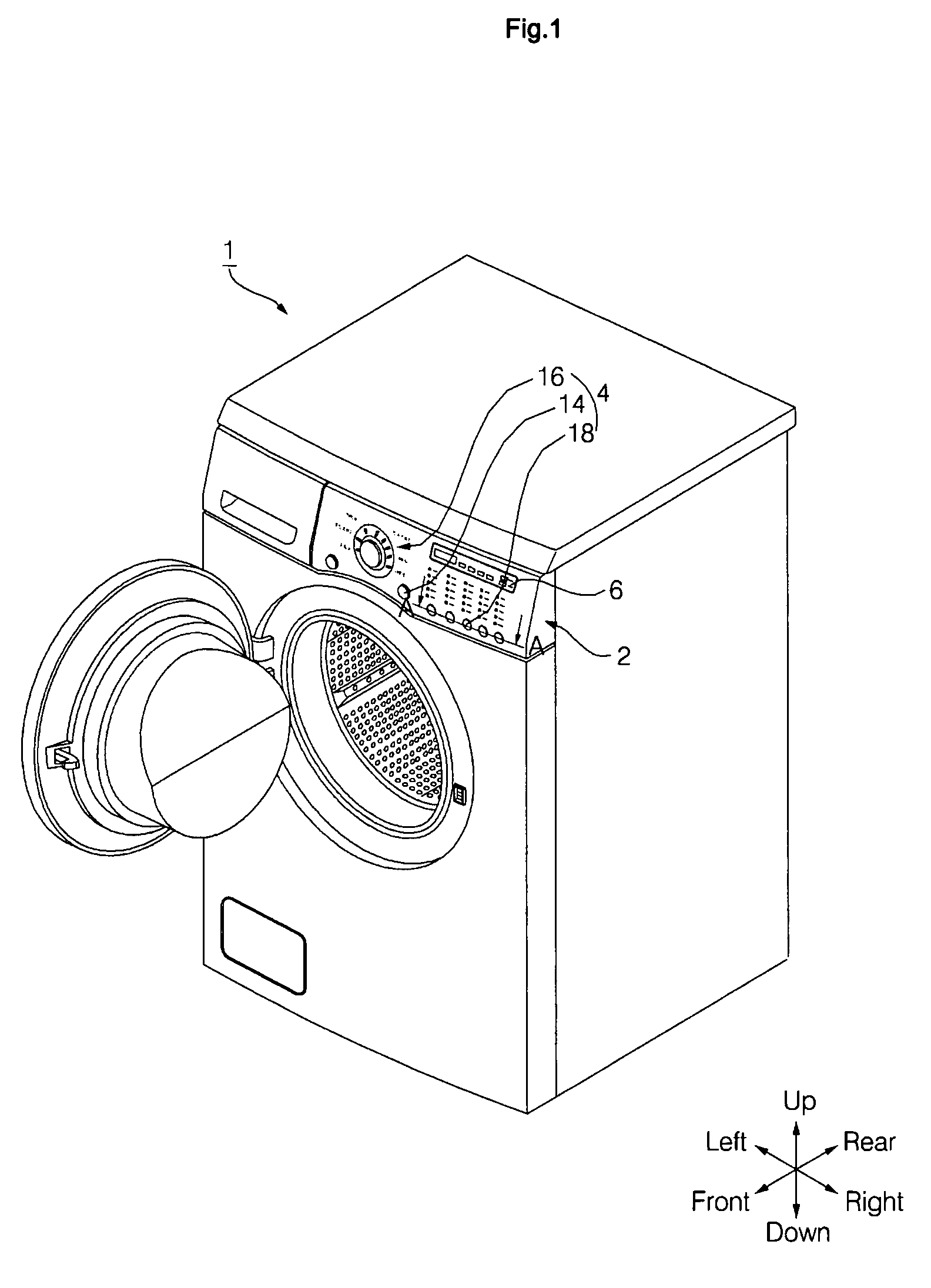
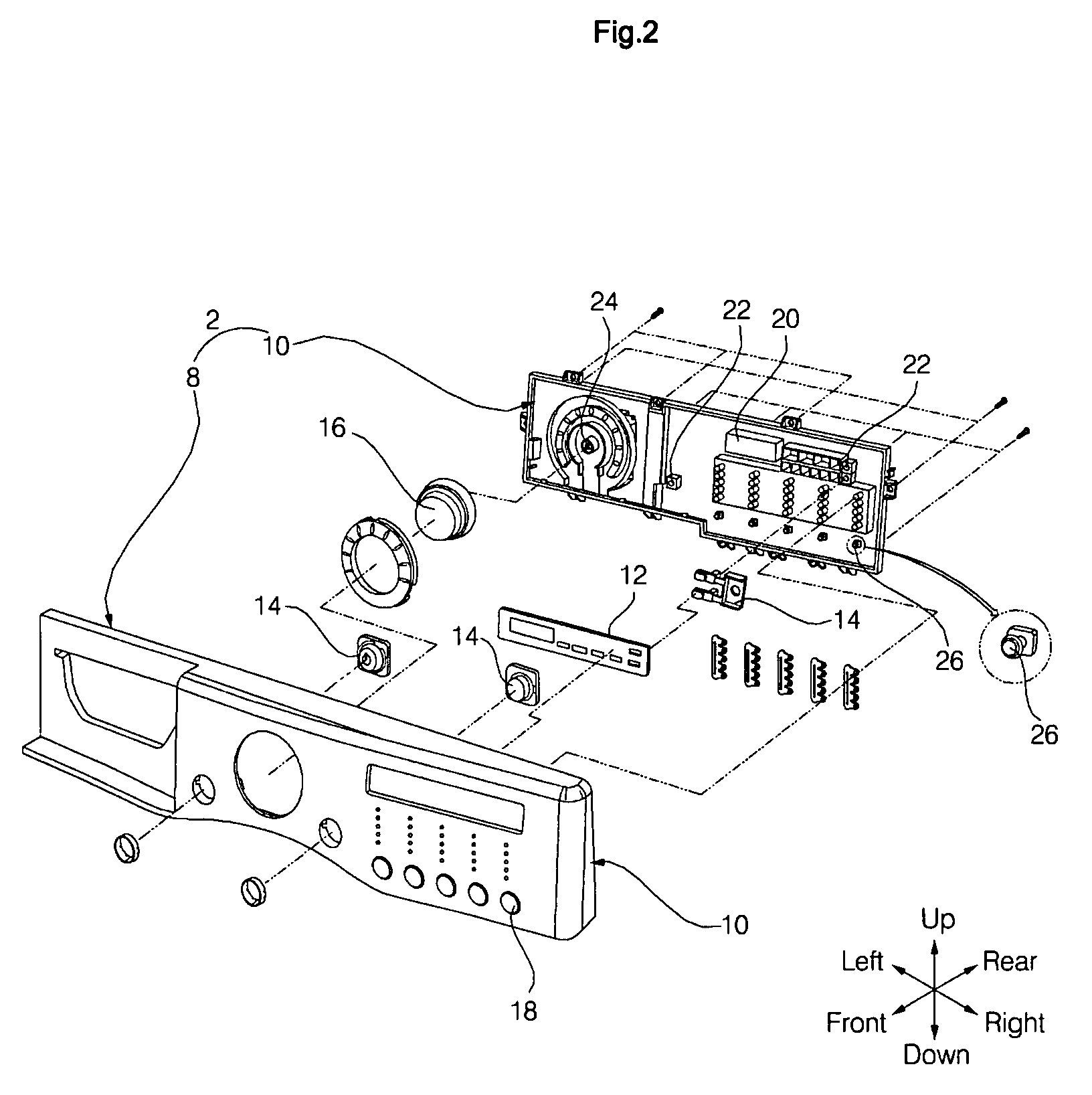
[0031]FIG. 1 is a perspective view of a washing machine 1 equipped with a capacitive switch 30 according to an embodiment of the present invention. FIG. 2 is an exploded perspective view of a controller 2 illustrated in FIG. 1. FIG. 3 is a cross-sectional view taken along line A-A of FIG. 1. FIG. 4 is an exploded perspective view of the capacitive switch 30 illustrated in FIG. 1. FIG. 5 is an exploded perspective view of a capacitive switch 30′ according to another embodiment of the present invention, which is a variation of the capacitive switch 30 illustrated in FIG. 1. More specifically, FIGS. 1 and 2 illustrate the washing machine 1 including the capacitive switch 30 and the controller 2.

[0032]Referring to FIG. 1, the controller 2 is installed at the front of an upper portion of the washing machine 1. The contro...


PUM


Abstract

A capacitive switch of an electric/electronic device is provided. The capacitive switch includes a plurality of contacts which are disposed at a front of a control panel; a plurality of capacitive sensors which are disposed at a rear of the control panel, respectively face the contacts, and detect capacitance variations caused by static electricity that affects the contacts; and a plurality of void removal elements which are respectively disposed between the capacitive sensors and the contacts, remove a plurality of voids between the capacitive sensors and the contacts, and are formed of an elastic material so as to be able to compensate for various sized voids. Therefore, it is possible to easily remove various sized voids between the contacts and the capacitive sensors using the void removal elements, to prevent malfunction of the capacitive sensors due to the existence of voids, and to provide various shapes of control panels and various shapes of printed circuit boards.

Description

[0001]This application claims priority from Korean Patent Application No. 10-2006-0052132 filed on Jun. 9, 2006 in the Korean Intellectual Property Office, the disclosure of which is incorporated herein by reference in its entirety.BACKGROUND OF THE INVENTION[0002]1. Field of the Invention[0003]The present invention relates to a capacitive switch of an electric / electronic device, and more particularly, to a capacitive switch of an electric / electronic device which can easily remove a plurality of voids between a plurality of contacts and a plurality of capacitive sensors.[0004]2. Description of the Related Art[0005]Electric / electronic devices are generally equipped with a controller which can control an electric / electronic device to perform an operation desired by a user. A controller of an electric / electronic device generally includes a manipulation unit which manipulates an operation of the electric / electronic device according to user manipulation, a display unit which displays inf...

Claims


Application Information

Patent Timeline
IPC IPC(8): H01L29/00H01G4/255
CPCH01H2229/064H01H2231/012H03K2217/96076H03K17/962H03K2217/96015H01H2239/006H01H13/26H01H13/70H01H13/7073
Inventor JEONG, HOI JIN
Owner LG ELECTRONICS INC
Why Eureka
Try Eureka