
System and method for shaping ultra wide bandwidth signal spectrum

a technology of transmission spectrum and transmission signal, applied in the field of wireless communication, can solve problems such as imposing additional constraints on the spectrum shaping

Active Publication Date: 2007-12-13
MITSUBISHI ELECTRIC RES LAB INC
View PDF2 Cites 7 Cited by
  • Summary
  • Abstract
  • Description
  • Claims
  • Application Information

AI Technical Summary

Problems solved by technology

All these requirements impose additional constraints on the spectrum shaping.
A null in the transmit spectrum also implies a null in the transfer function of the matching filter, and thus interference suppression at this frequency.

Method used


Image

  • System and method for shaping ultra wide bandwidth signal spectrum
  • System and method for shaping ultra wide bandwidth signal spectrum
  • System and method for shaping ultra wide bandwidth signal spectrum

Examples


Embodiment Construction

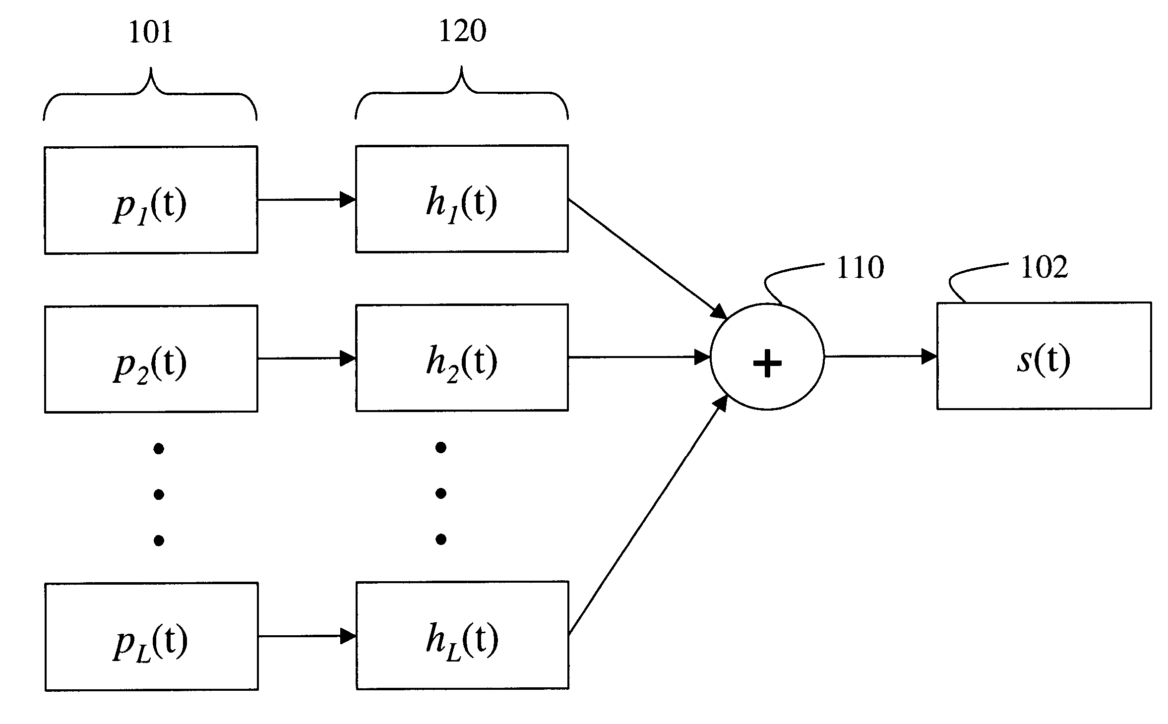
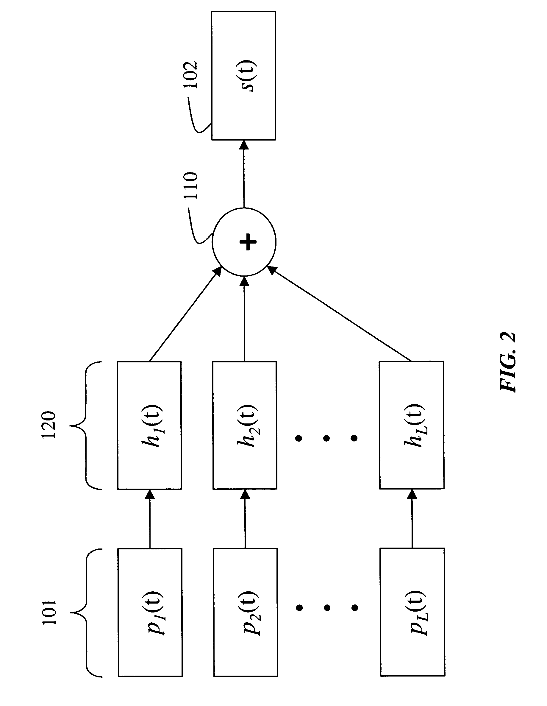
[0020] As shown in FIG. 2, our invention uses a linear combination 110 of a set of basis pulses 101 for shaping of a spectrum a transmitted impulse radio signal, s(t) 102, for example, a transmitted ultra wide bandwidth (UWB) signal. The basis pulses 101 are generated using circuits so that they are spread over the frequency spectrum with pseudo random delays.

[0021] Prior to the combining 110, a set of optimized filter and delay lines 120, hl(t), l=1, . . . , L, is applied to the pulses to weight and delay the generated basis pulses to conform to a predetermine spectral mask.

[0022] The combination of the filtered pulses can be achieved by a combination of analogue delay lines, adders, and programmable pulse generators.

[0023] As shown in FIG. 3, our invention can also apply a set of oscillators 310 to the output of the filters 120 to shift the frequency, if necessary. The oscillators are of the form cos(Ωit+Φi). Frequency shifting enables an additional degree of freedom in the des...


PUM


Abstract

A method and system shapes a spectrum of an impulse radio signal, such as an UWB signal. First, basis pulses at various frequencies and pseudo-random delays are generated. The generated set of basis pulses are then weighted and delayed, and combined linearly to conform the spectrum of the transmitted basis pulses to a spectral mask. The spectral mask can be predetermined, or the conforming can be adaptive. Furthermore, the basis pulses can be frequency-shifted before the combining.

Description

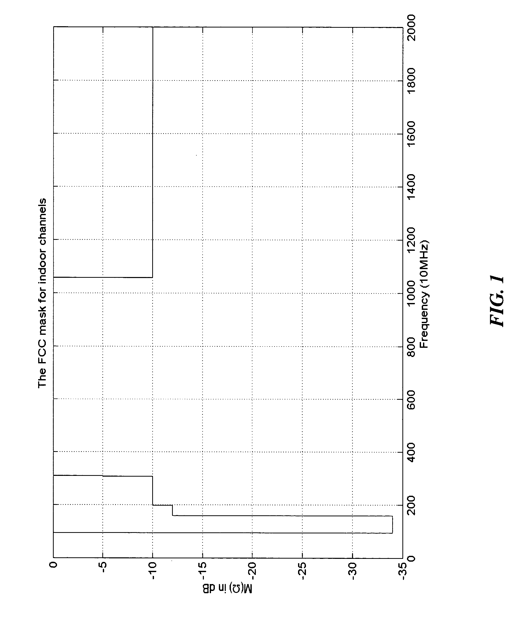
CROSS REFERENCE TO RELATED APPLICATION [0001] A claim of priority is made to U.S. provisional application Ser. No. 60 / 451,577, “UWB Communication system with shaped signal spectrum by pulse combination,” filed Mar. 3, 2003.FIELD OF THE INVENTION [0002] This invention relates generally to wireless communications, and more particularly to shaping the spectrum of transmitted signals in ultra wide bandwidth communication systems. BACKGROUND OF THE INVENTION [0003] With the release of the “First Report and Order,” Feb. 14, 2002, by the Federal Communications Commission (FCC), interest in ultra wide bandwidth (UWB) communication systems has increased. The IEEE 802.15 standards organization, which is responsible for personal area networks (PAN), has established a task group, TG3a, to standardize a high-data-rate physical layer based on UWB. One of the most important requirements is compliance with the FCC spectral mask for indoor channels shown in FIG. 1. The spectral mask shows power limi...

Claims


Application Information

Patent Timeline
Patent Type & Authority Applications(United States)
IPC IPC(8): H04B1/00
CPCH04B1/7172
Inventor MOLISCH, ANDREASWU, YUNNANKUNG, SUN Y.
Owner MITSUBISHI ELECTRIC RES LAB INC
Learn More