Lever type electrical connector

a technology of lever actuators and connectors, which is applied in the direction of coupling device connections, coupling parts engagement/disengagement, electrical apparatus, etc., can solve the problems of insufficient mechanical advantage provided by lever actuators, inability to effectively mate or unmate large connectors, and difficulty in hand-held operation, etc., to achieve precise force transfer system, large output force, and substantial constant load

Active Publication Date: 2007-12-13
MOLEX INC
View PDF4 Cites 13 Cited by
  • Summary
  • Abstract
  • Description
  • Claims
  • Application Information

AI Technical Summary

Benefits of technology

[0014] The lever actuator includes a predetermined force transmitting engagement portion at which the lever actuator engages the other connector to transmit a leveraged output force thereto upon the pivoting of the lever actuator from the release position to the lock position. A first, fixed predetermined distance is provided between the force input end of the lever actuator and the pivot connection and a second, fixed predetermined distance is provided between the force transmitting engagement portion and the pivot connection that is smaller than the first, fixed predetermined distance. A fixed, predetermined leverage ratio is defined by dividing the larger, first fixed predetermined distance by the smaller, second fixed predetermined distance. This leverage ratio stays substantially constant during pivoting of the lever actuator from the release position to the lock position. In this manner, with a constant actuation force applied to the force input end of the lever actuator, a known constant output force will be generated on the other connector allowing for a more precise force transfer system to be designed for the connector assembly herein.
[0015] In this regard, an electrical connector assembly is provided that is configured to precisely maximize and concentrate the mechanical advantage provided by the actuating or assist lever. It is preferred that the connector assembly be configured to provide an output force of at least about 300 N with a user input force of only about 75 N or less on a force-input end of the actuating lever. The connectors herein, therefore, are able to generally comply with automotive industry standards because lower levels of input forces can be used to mate even large connectors, such as those with at least 90 pin contacts.
[0016] The constant leverage ratio can be precisely set via the fixed distances along the lever actuator to provide a large output force that is achieved with lower levels of actuation force being applied to the force-input end of the lever by the user. In one form, the predetermined leverage ratio is approximately 7:1. In another form, the predetermined leverage ratio is sufficient to achieve the leveraged output force of approximately 300 N or greater with the actuation force being approximately 75 N or less.

Problems solved by technology

For instance, frictional forces encountered during connecting and disconnecting the connectors may make the process difficult to perform by hand.
It has been found that current lever-actuator configurations can not effectively mate or un-mate large connectors such as described above while keeping user input force at or below the level specified by the industry standard.
With current lever connector configurations, the mechanical advantage provided by the lever actuators is not sufficient to overcome the high frictional forces seen by large electrical connector assemblies between pins and sockets of the connectors as they are mated and un-mated.
At the interface between the cam projection and grooves, there are inefficiencies generated in the force transfer between the input force applied to the lever and the output force applied by the lever to the other connector requiring greater efforts by the user than as desired for mating and unmating the connectors together.
The configuration of the interface between the cam of the lever and the camming surface of the header electrical connector of the '330 electrical assembly connector is not suitable for larger connectors because the lever does not generate a sufficient mechanical advantage using only 75 N or less of input force to shift the connectors to a mated position relative to each other.
Such a curved surface does not provide a fixed contact location between the curved cam surface of the lever and cam surface area of the header connector as the lever is pivoted, but instead generates a rolling action in the cam surface area so that the leverage and output force generated by pivoting of the lever for mating the connectors together is variable.
This makes precision design of such a lever to provide the mechanical advantage necessary for mating of large connector assemblies extremely difficult.
In addition, the variable engagement of the curved cam force transmitting surfaces generates an inefficient transfer of forces therebetween.
Since the thin lever arms are used to generate the output force for mating and unmating the connectors, generally it is undesirable to have these lever arms be flexed or deformed during pivoting of the lever actuator.

Method used


Image

  • Lever type electrical connector
  • Lever type electrical connector
  • Lever type electrical connector

Examples


Embodiment Construction

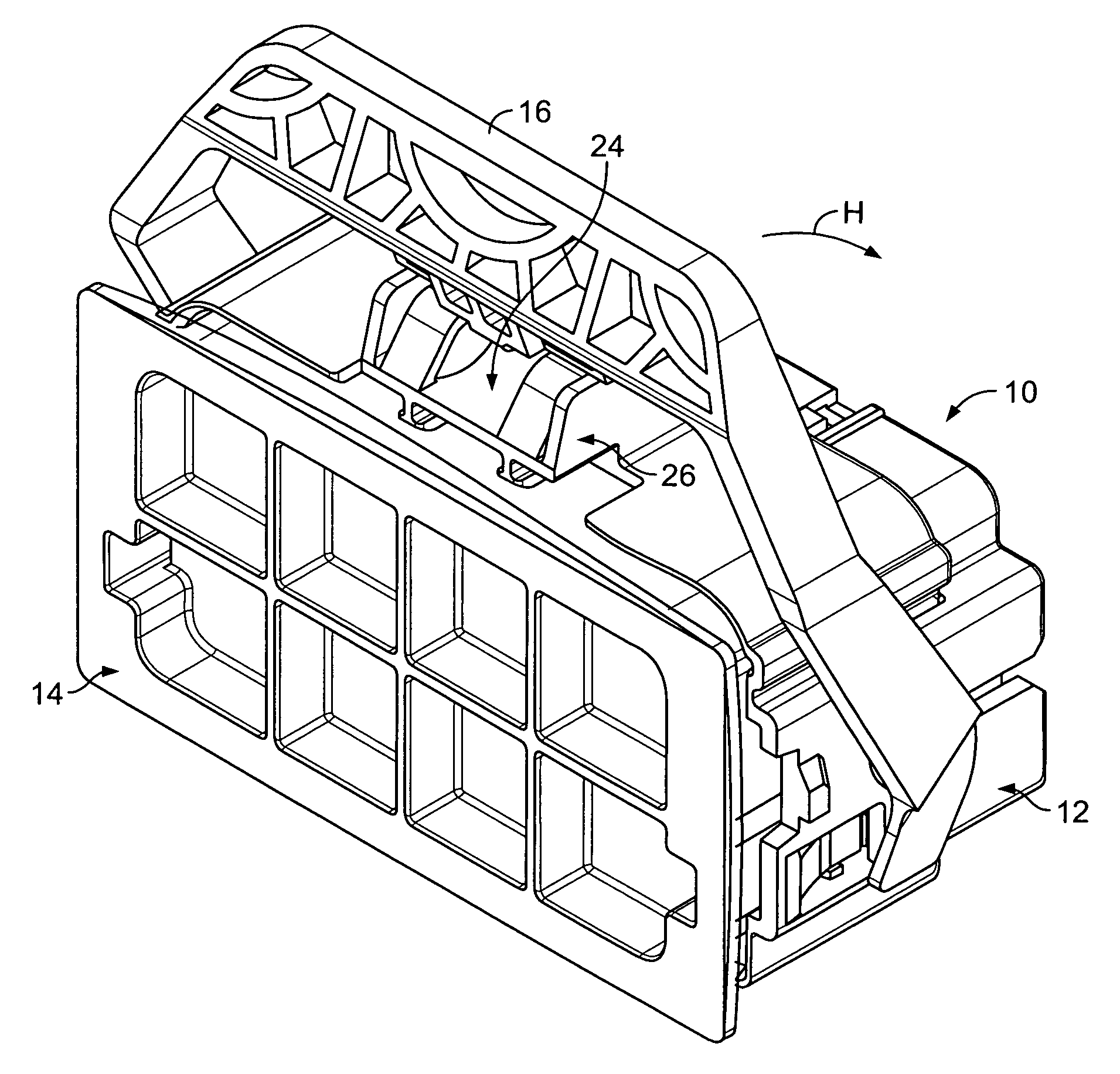
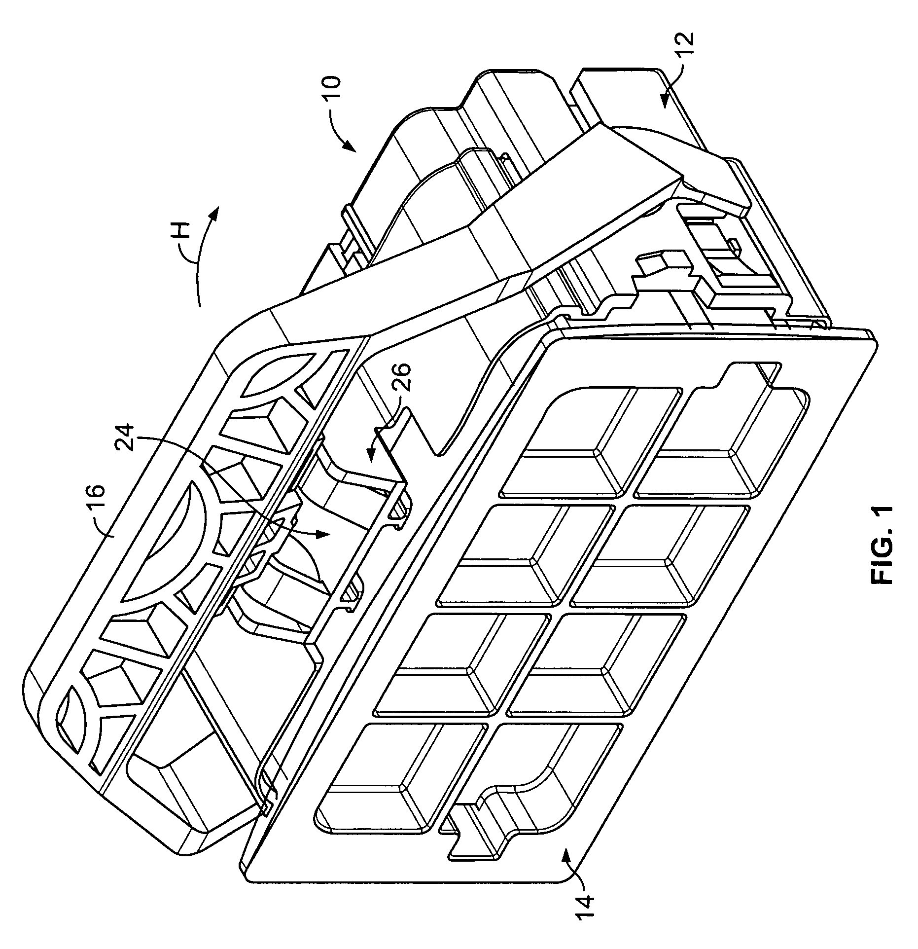
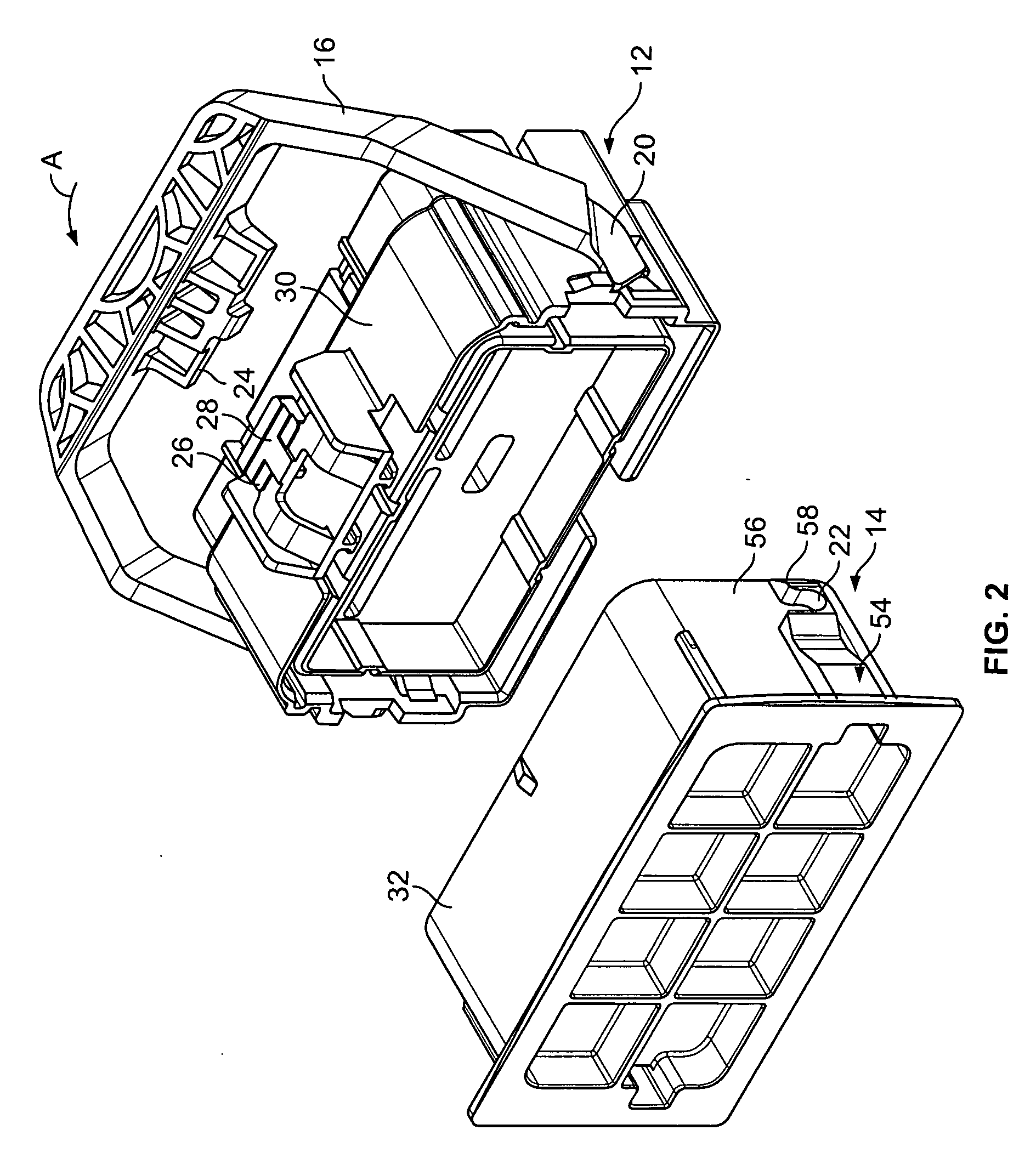
[0045] Referring to the drawings in greater detail, and first to FIGS. 1 and 2, a lever-type electrical connector assembly 10 is illustrated that includes a first connector or housing 12 and a second connector or header 14. Each connector 12 and 14 includes a plurality of electrical contacts (not shown) received therein. Preferably, the assembly 10 includes greater that 90 electrical contacts and, when assembled, is at least 70 mm wide, 60 mm long, and 60 mm high. In one preferred example, the connector 10 may include 98 electrical contacts and be configured as a harness connector for diesel engines; however, other uses, sizes, and configurations of the connector 10 are also possible.

[0046] Connectors of such size and configuration typically require greater than about 300 N of force to overcome frictional and engagement forces in order to mate or un-mate the header 14 and the housing 12. To this end, the connector 10 further includes a lever actuator 16 having a first, pre-mate, or...


PUM


Abstract

A lever-type electrical connector assembly is provided that includes first and second electrical connectors having an actuating lever movably mounted thereon for movement between a release position with the connectors un-mated and a lock position with the connectors mated. In one form, a blocking member is provided between the first connector and the actuating lever for holding the actuating lever in the release position. A second connector includes a release member for shifting the blocking member to allow the actuating lever to move from the release position to the lock position. In another form, the electrical connector assembly is configured to precisely maximize the mechanical advantage provided by the actuating lever by including a predetermined force transmitting engagement portion at which the lever actuator engages one of the connectors to transmit a concentrated, predetermined leveraged output force thereto upon pivoting of the lever from the release to the lock position.

Description

CROSS-REFERENCE TO RELATED APPLICATION [0001] This application claims benefit of U.S. Provisional Application No. 60 / 811,943, filed Jun. 8, 2006, which is hereby incorporated herein by reference in its entirety.FIELD OF THE INVENTION [0002] This invention generally relates to electrical connector assemblies and, more particularly, to an electrical connector assembly including electrical connectors that are matingly connected and disconnected by operation of a lever actuator of one of the connectors. BACKGROUND OF THE INVENTION [0003] A typical lever-type electrical connector includes an assembly of a first connector or housing and a second connector or header. To mate the connectors together, the assembly has an actuating or assist lever mounted for pivoting on the first connector with pivoting of the lever causing the first and second connectors to shift between unmated and fully mated configurations. To this end, the actuating lever and the second connector typically have a cam gr...

Claims


Application Information

Patent Timeline
Patent Type & Authority Applications(United States)
IPC IPC(8): H01R13/62
CPCH01R13/62955H01R13/62938
Inventor DEKOSKI, KURT P.LANGOLF, DAVID L.DOLINSHEK, THOMAS
Owner MOLEX INC
Why Eureka
Try Eureka