Fuel spraying apparatus of gas turbine engine

a gas turbine engine and fuel spraying technology, which is applied in the direction of lighting and heating apparatus, machines/engines, efficient propulsion technologies, etc., can solve the problems of increased generation of nox (nitrogen oxide), degraded ignitability and combustibleness and deficient combustion stability at a low load. achieve the effect of improving ignitability, flamability, and particularly combustion stability

Active Publication Date: 2007-12-20
KAWASAKI HEAVY IND LTD
View PDF9 Cites 65 Cited by
  • Summary
  • Abstract
  • Description
  • Claims
  • Application Information

AI Technical Summary

Benefits of technology

[0026] The fuel spraying apparatus of a gas turbine engine of the present invention is structured as mentioned above, so that it can produce an excellent effect of improving ignitableness, flamableness, and particularly combustion stability at a low load in a combustor to which the composite combustion system combining two kinds of combustion systems of the diffusion combustion system and lean combustion system is applied.

Problems solved by technology

As a result, an increase in the generation amount of NOx (nitrogen oxide), which is one of the harmful material aforementioned, is caused.
However, the aforementioned lean combustion system to realize low NOx is deficient in combustion stability at a low load.
Namely, the lean combustion system is required to introduce a large amount of air from the fuel spraying apparatus, so that the local fuel density in the combustion area is greatly lowered than the fuel density at the diffusion combustion system, and a problem arises that the ignitableness and combustibleness at a low load are degraded.
However, in the composite combustion system, a large amount of air introduced for lean combustion adversely affects combustion by the diffusion combustion system.
Due to this adverse effect, a problem arises in combustion by the diffusion combustion system that sufficient ignitableness and flamableness and the combustion stability at a low load may not be obtained.
Particularly, for an airplane gas turbine, sure ignition is required under the condition of low temperature and low pressure at a high altitude, and emission at a low load at time of idling is regulated in various aspects, so that the degradation in the ignitableness and combustion stability due to air introduced for lean combustion may come Into a greater problem.

Method used


Image

  • Fuel spraying apparatus of gas turbine engine
  • Fuel spraying apparatus of gas turbine engine
  • Fuel spraying apparatus of gas turbine engine

Examples


embodiment 1

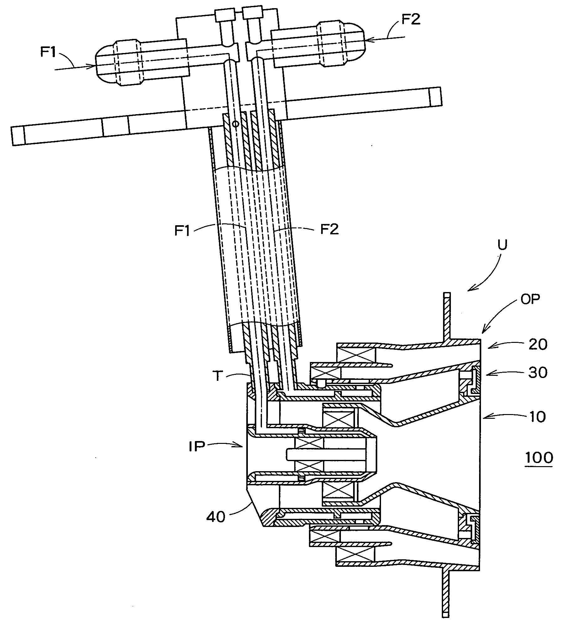
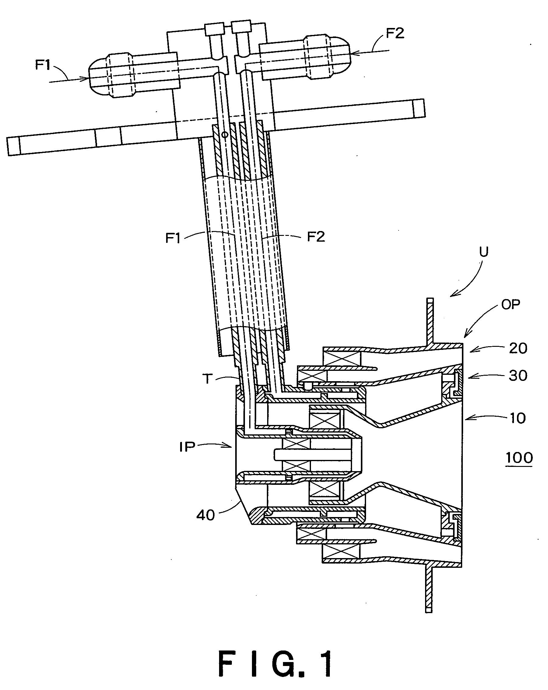
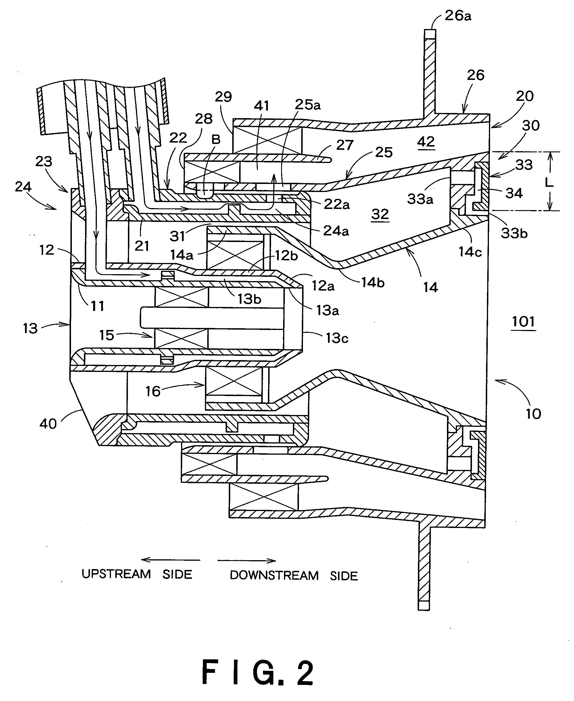
[0041] Referring to FIGS. 1 to 3, a fuel spraying apparatus U is installed in a combustor 100 of a gas turbine engine. The fuel spraying apparatus U includes a first fuel spraying section 10, a second fuel spraying section 20, and an air curtain generating section 30. The first fuel spraying section 10 is configured to spray fuel for diffusion combustion from a first fuel supply system F1 toward a diffusion combustion area A1. The a second fuel spraying section 20 is installed so as to surround the first fuel spraying section 10 in the radial direction thereof. The second fuel spraying section 20 is configured to spray fuel while premixing the same for lean combustion from a second fuel supply system F2 toward a premixed combustion area A2. The air curtain generating section 30 is configured to generate an air curtain for defining the outer edge of the diffusion combustion area A1.

[0042] Here, the fuel spraying apparatus U has an almost axially symmetric structure, so that in the d...

embodiment 2

[0069]FIG. 7 shows a fuel spraying apparatus U1 according to Embodiment 2 of the present invention. Embodiment 2 is made by modifying Embodiment 1, that is, the first fuel spraying section 10 of Embodiment 1 for diffusion combustion is modified. The constitution other than a first fuel spraying section 10A is the same as that of Embodiment 1, so that the same numerals are assigned and detailed explanation will be omitted.

[0070] The first fuel spraying section 10A, as shown in FIG. 7, includes a closed-end cylindrical main unit 51 for supplying fuel for diffusion combustion. A cylindrical inner peripheral wall 52 is fit into the main unit 51. A cylindrical intermediate wall 53 is arranged concentrically outside the cylindrical inner peripheral wall 52. A Venturi spraying nozzle member 54 is arranged concentrically outside the cylindrical intermediate wall 53. An inner swirler 55 is arranged between the cylindrical inner peripheral wall 52 and the cylindrical intermediate wall 53. An...

embodiment 3

[0081]FIG. 8 shows a fuel spraying apparatus U2 according to Embodiment 3 of the present invention. Embodiment 3 is made by modifying Embodiment 2, that is, the first fuel spraying section 10A for diffusion combustion of Embodiment 2 is modified. Namely, in a first fuel spraying section 10B of Embodiment 3, the upstream ends of the cylindrical inner peripheral wall 52 and cylindrical intermediate wall 53 coincide with the upstream end of the spraying nozzle member 54, and the inner swirler 55 is made smaller, thus the influence force thereof, i.e., the rotation force is lowered.

[0082] Further, the other constitution, operation, and effects are the same as those of Embodiment 2, so that detailed explanation thereof will be omitted.

[0083] As mentioned above, according to Embodiment 3, the influence of the inner swirler 55 is reduced, so that the angular control by the spraying nozzle member 54 is executed more surely, thus stabler diffusion combustion can be realized.


PUM


Abstract

A fuel spraying apparatus of a gas turbine engine includes a first fuel spraying section configured to spray fuel for diffusion combustion and a second fuel spraying section configured to spray fuel for premixed combustion. The second fuel spraying section is disposed so as to surround the first fuel spraying section. The apparatus further includes an air curtain generating section disposed between the first fuel spraying section and the second fuel spraying section. The air curtain generating section configured to generate an air curtain which defines an outer edge of a diffusion combustion area in a combustion chamber.

Description

CROSS-REFERENCE TO RELATED APPLICATIONS [0001] This application is based upon the prior Japanese Patent Application No. 2005-3.58357 filed on Dec. 13, 2005, the entire contents of which are incorporated herein by reference. BACKGROUND OF THE INVENTION [0002] 1. Field of the Invention [0003] The present invention relates to a fuel spraying apparatus of a gas turbine engine and more particularly to a fuel spraying apparatus of a gas turbine engine for realizing stabler combustion in composite combustion combining two kinds of combustion systems of a diffusion combustion system and a lean combustion system. [0004] 2. Description of the Related Art [0005] It is an urgent necessity for environmental conservation to reduce harmful material ejected by combustion of an internal combustion engine. However, in a gas turbine engine, particularly in a large engine or an airplane engine, the pressure ratio is apt to increase on demand of realization of high output, and in correspondence to it, r...

Claims


Application Information

Patent Timeline
Patent Type & Authority Applications(United States)
IPC IPC(8): F23R3/14
CPCF23C2900/07022F23D11/383F23D2900/00008F23D2900/11101F23R3/14Y02T50/675F23R3/286F23R3/343F23R2900/00017F23R2900/00019F23R3/283Y02T50/60
Inventor ODA, TAKEONINOMIYA, HIROYUKIOGATA, HIDEKI
Owner KAWASAKI HEAVY IND LTD
Why Eureka
Try Eureka