
Well head valve insulator

insulator technology, applied in the field of removable insulation, can solve the problems of additional cost and labor, the prefabrication of a well head valve insulator is not a practical alternative, and the cost and labor of replacing insulation, etc., and achieve the effect of reducing the cost and labor of replacement, reducing the cost of replacement, and improving the service li

Inactive Publication Date: 2007-12-20
CHITWOOD BILL +1
View PDF19 Cites 8 Cited by
  • Summary
  • Abstract
  • Description
  • Claims
  • Application Information

AI Technical Summary

Benefits of technology

The well head valve insulator is a special insulator designed to protect gas or oil well heads. It is made up of two pieces of rigid or semi-rigid material that are custom-fitted to the well head and filled with foam insulation. The insulator can be opened and reclosed for routine maintenance. It can also have a heating element to periodically heat the valve and a temperature sensor to monitor the well head. The method of making the insulator involves forming the outer shell, mounting the heating coil support, installing the heating coil, closing the shell around the well head, injecting foam insulation, and separating the inner foam insulation with a flexible wire cutter. The technical effect of this invention is to provide better insulation and protection for gas or oil well heads, allowing for safer and more efficient operation.

Problems solved by technology

Thus, prefabrication of a well head valve insulator is not a practical alternative.
The insulation must be cut away and discarded to perform such maintenance, exposing the maintenance workers to health hazards from diseases spread by the pests that nest in the insulation, and incurring additional cost and labor to replace the insulation.
While various insulators for gas and oil delivery pipes have been proposed, none have been found entirely satisfactory.

Method used


Image

  • Well head valve insulator
  • Well head valve insulator
  • Well head valve insulator

Examples


Embodiment Construction

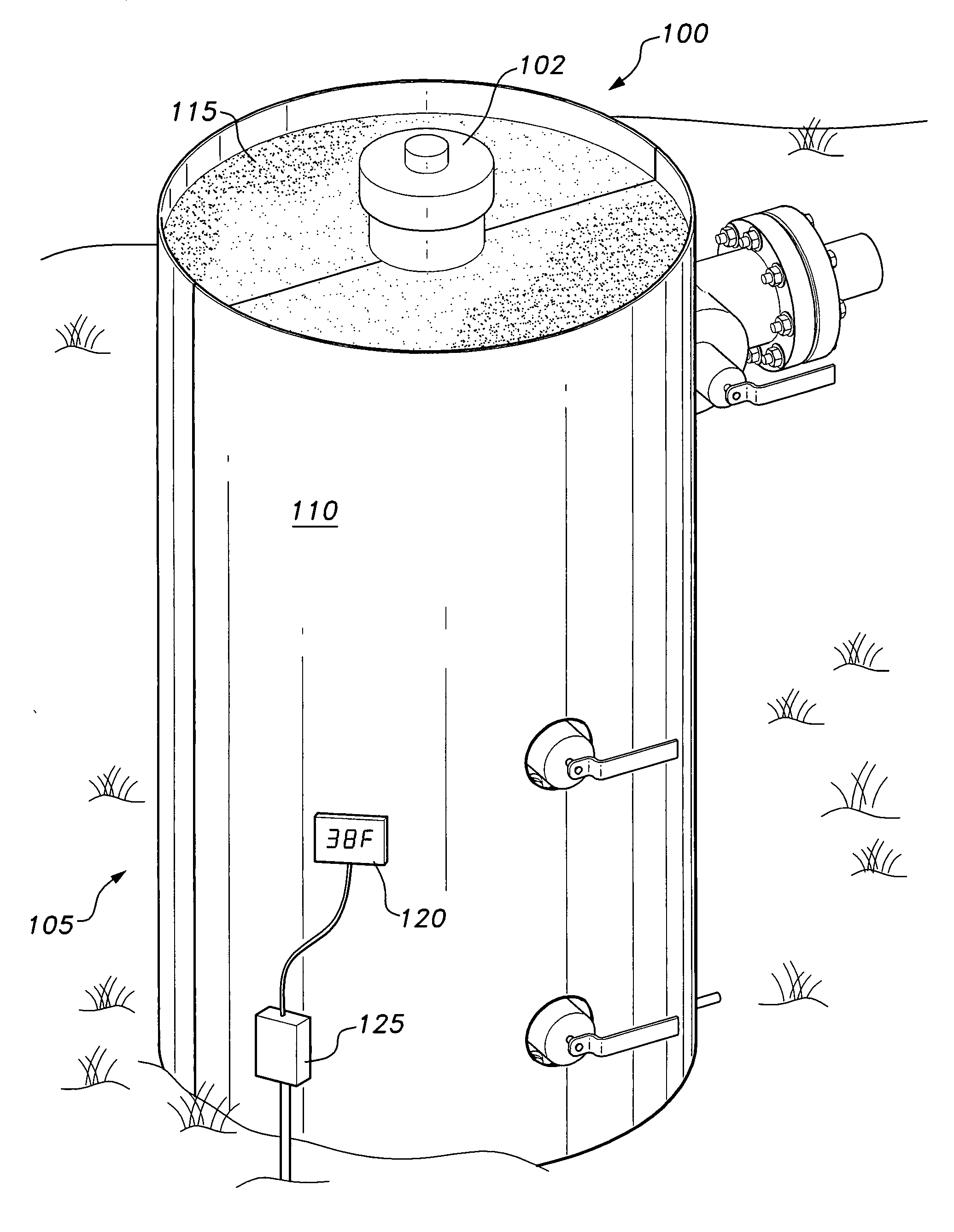
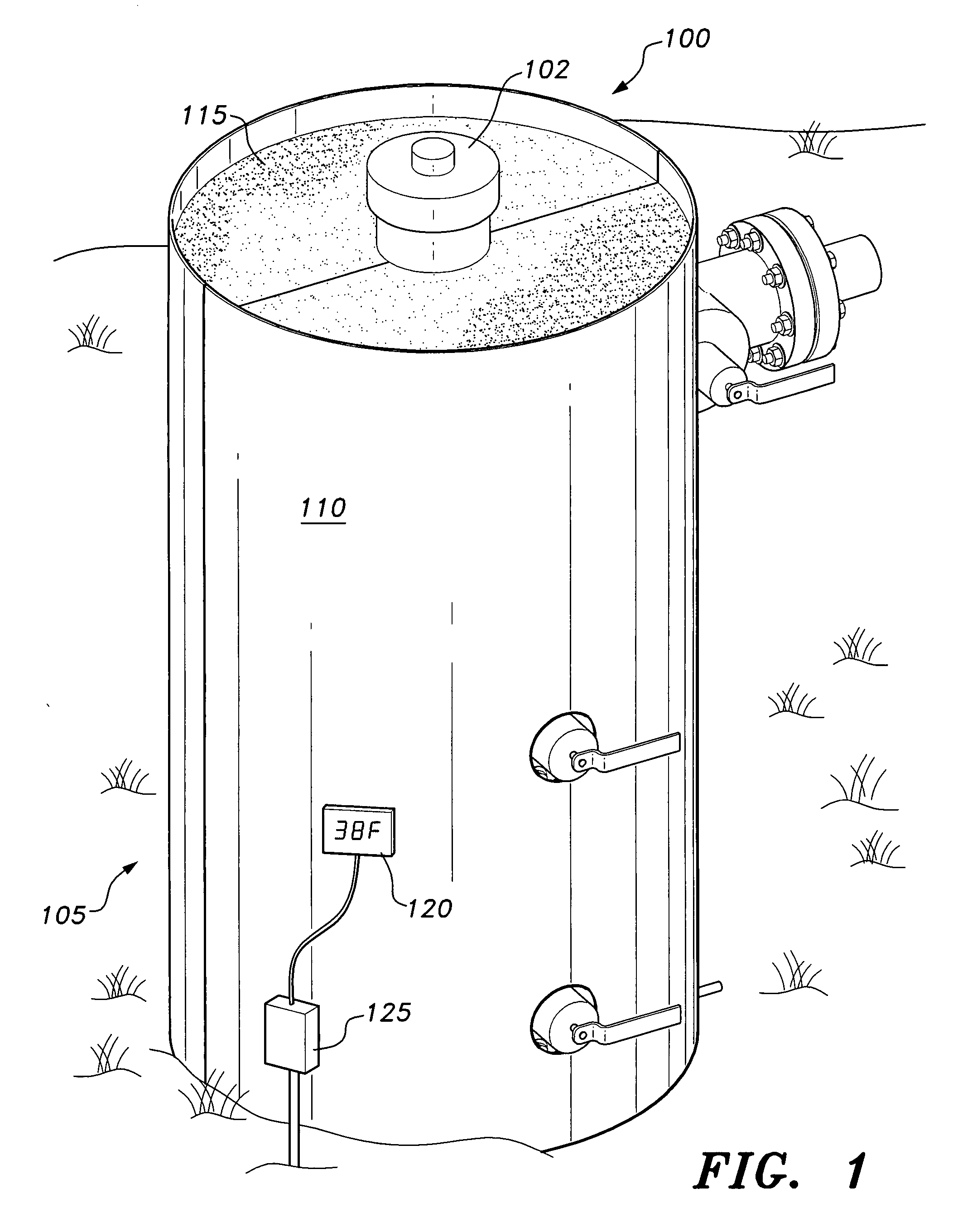
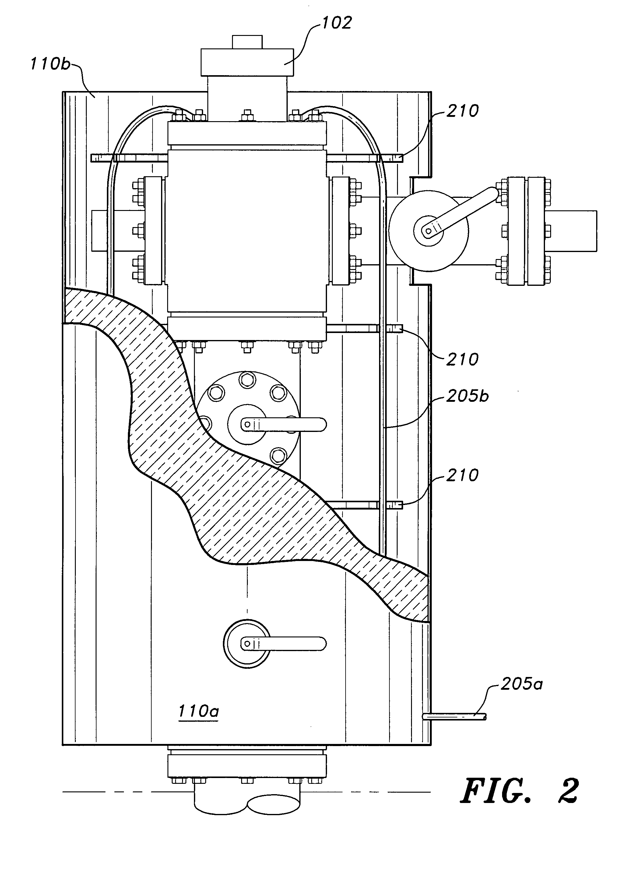
[0017]The present invention, as shown in FIG. 1, is a well head valve insulator, designated generally as 105 in the drawings, comprising an inner layer of foam insulation 115 surrounded by a rigid outer shell enclosure 110. The rigid outer shell 110 is composed of a plurality of shell sections 110a and 110b shaped to enclose the well head 102 laterally. The shell enclosure 110 may have apertures or cutouts disposed relative to one another so that protruding members of the well head 102 may pass through the cutout apertures when the shell 110 is erected around the well head 102. As shown in FIG. 2, in order to make installation and removal an easy one person job, the shell sections 110a, 110b are preferably formed as two semi cylindrical shells that form a cylindrical tube around the well head, although, as shown in FIG. 4, a rectangular outer shell 410 may also be used. It should be noted that the outer shell may be cylindrical, square, rectangular, or other polygonal configuration....


PUM


Abstract

The well head valve insulator provides insulation to a gas or oil well head. The insulator is formed with a two-piece outer shell that has a height and diameter custom-fitted to the well head, which is filled with foam insulation, preferably polyurethane foam that is molded to the configuration of the particular well head. The insulator includes heating element supports for supporting a hose or heating coil that is used to periodically heat the valve through the flow of warm fluid. The two halves of the insulator can be opened and reclosed around the well head in order to provide access for routine maintenance. Optionally, the insulator may be furnished with a temperature sensor for monitoring the temperature of the well head, or with a thermostatic control for regulating heat delivered by the heating coil.

Description

CROSS-REFERENCE TO RELATED APPLICATION[0001]This application claims the benefit of U.S. Provisional Patent Application Ser. No. 60 / 814,555, filed Jun. 19, 2006.BACKGROUND OF THE INVENTION[0002]1. Field of the Invention[0003]The present invention relates to removable insulation for fittings, in a fluid flow system, and more particularly to a well head valve insulator for insulating the valves in a natural gas well head.[0004]2. Description of the Related Art[0005]In insulating piping systems used for transmission of gases and / or fluids in cold climates, insulation may be provided for cylindrical piping. In the case of a gas well head, for example, there exist various elements, such as flanges, tees, elbows, reducers, valves, and the like, that protrude from the generally cylindrical shape of the main pipe, so that the well head is often referred to as a tree.[0006]The valves in the well head assembly are custom-fitted to accommodate various pressures that may be encountered at the we...

Claims


Application Information

Patent Timeline
Patent Type & Authority Applications(United States)
IPC IPC(8): F16L59/00
CPCF16L59/161Y10T137/6606Y10T137/7036
Inventor CHITWOOD, BILLCHITWOOD, JEROME D.
Owner CHITWOOD BILL
Learn More