Webbing retracting device

Active Publication Date: 2007-12-20
KK TOKAI RIKA DENKI SEISAKUSHO
View PDF9 Cites 25 Cited by
  • Summary
  • Abstract
  • Description
  • Claims
  • Application Information

AI Technical Summary

Benefits of technology

[0034]As explained above, the webbing retracting device according to the present invention can extremely effectively prevent the so-called e

Problems solved by technology

However, just after completion of taking up the webbing belt by the reel shaft if the lock mechanism is unintentionally actuated, then the reel shaft is not able to rotate in the pull out direction fr

Method used


Image

  • Webbing retracting device
  • Webbing retracting device
  • Webbing retracting device

Examples


first exemplary embodiment

[0057]

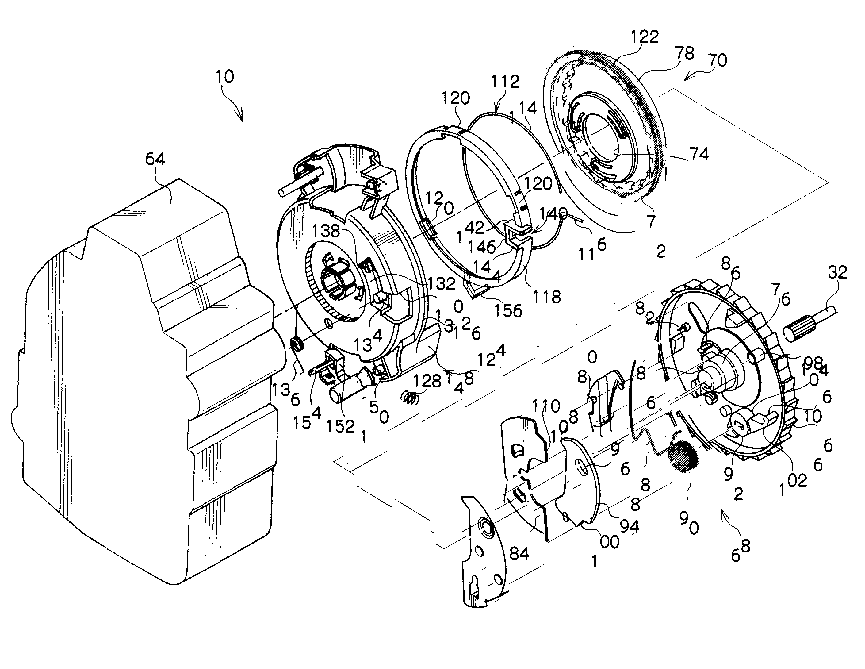
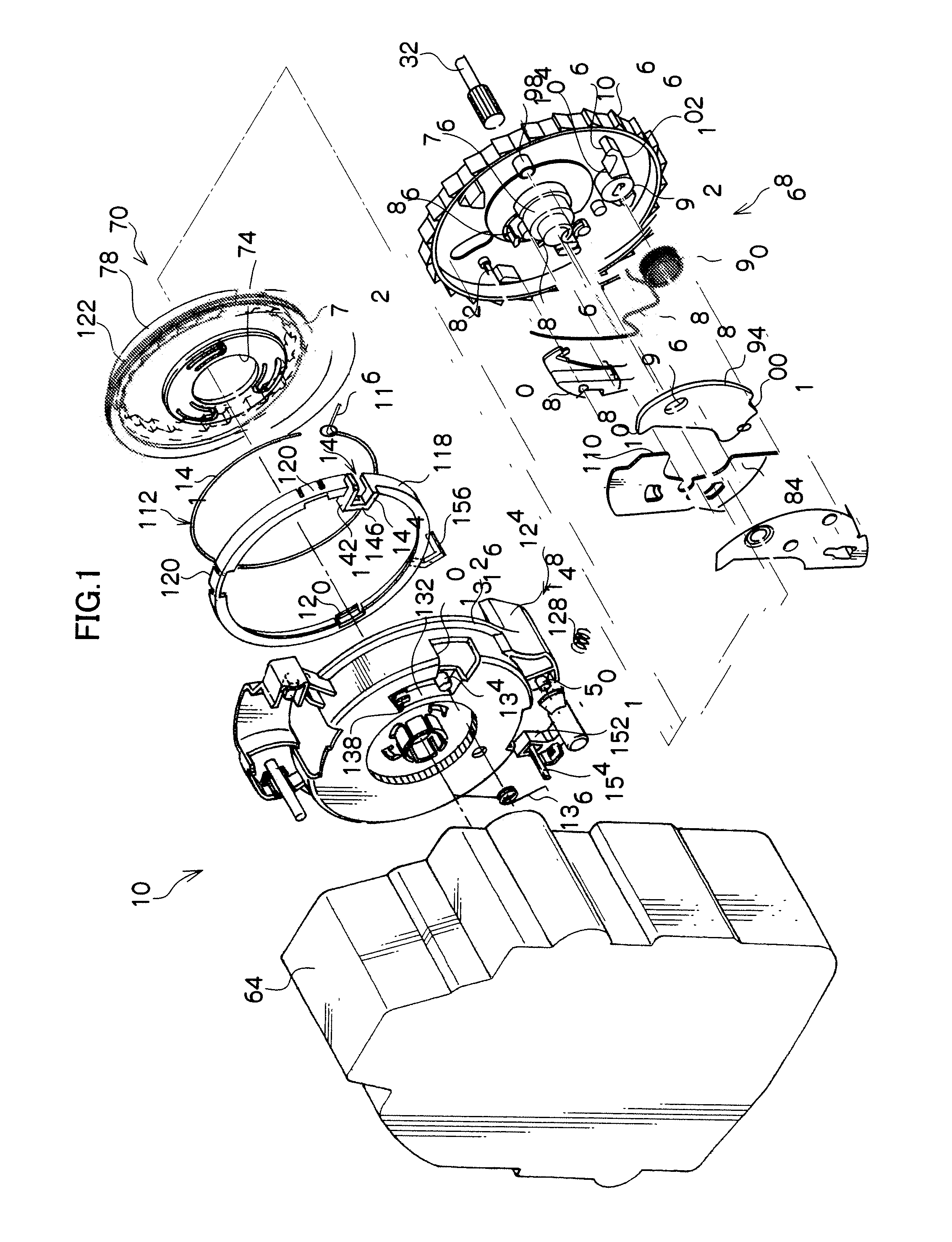
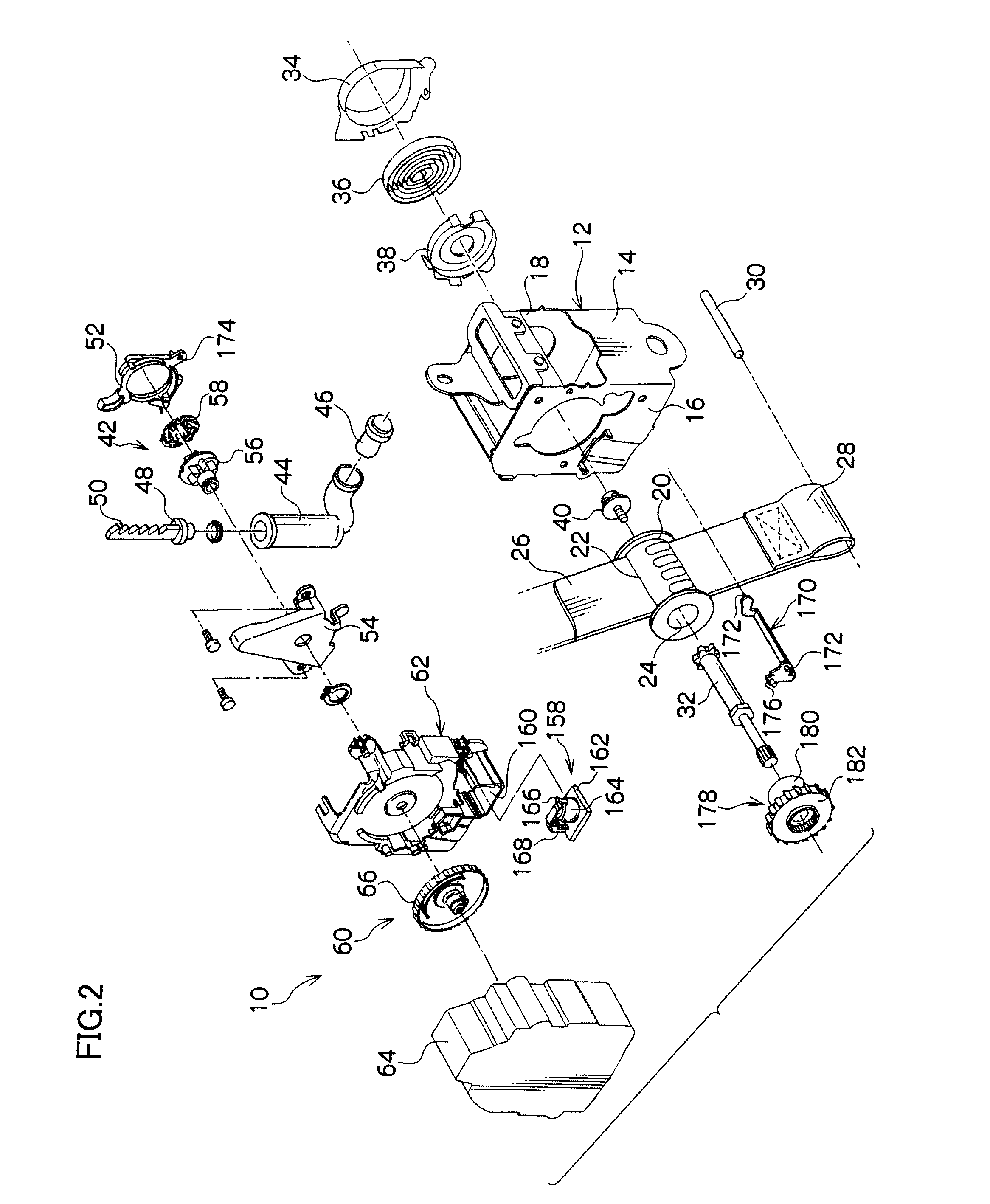
[0058]In FIG. 2 the overall outline configuration of a webbing retracting device according to a first exemplary embodiment of the present invention is shown through an exploded perspective view.

[0059]As is shown in the figure, a webbing retracting device 10 is provided with a frame 12. The frame 12 is, for example, provided with a back plate 14 that is a plate shape with a thickness direction thereof that is in the substantially left-right direction of a vehicle. The present webbing retracting device 10 is a structure that is attached to a vehicle body, by the back plate 14 being fixed with fasteners, such as bolts or the like, for example, to a vehicle body in the vicinity of a lower end of a center pillar. A leg plate 16 is formed from one width direction side of the substantially vehicle front-rear direction back plate 14, bent around toward the inside in the width direction of the vehicle (substantially the vehicle left-right direction). Also, a leg plate 18 is formed at t...

second exemplary embodiment

[0115]

[0116]In FIG. 6 a configuration of relevant portions of a webbing retracting device 200 according to a second exemplary embodiment of the present invention is shown through an exploded perspective view, and in FIG. 7 a configuration of relevant portions of the webbing retracting device 200 is shown through a front view.

[0117]The webbing retracting device 200 according to the present exemplary embodiment is substantially of the same configuration as the above first exemplary embodiment, but differs in the following points.

[0118]In the webbing retracting device 200, in the rotation detection mechanism 68, a circular column engagement pin 80A is integrally formed at the other end of the W pawl 80, and the engagement pin 80A projects from the W pawl 80 toward the opposite side to that of the V gear 66.

[0119]There is an engagement hole 84A formed through a outer peripheral portion of the inertial mass 84 at the take up direction side, and the engagement hole 84A is open to the oute...

third exemplary embodiment

[0138]

[0139]In FIG. 10 a configuration of relevant portions of a webbing retracting device 300 according to a third exemplary embodiment of the present invention is shown through an exploded perspective view, and in FIG. 11 a configuration of relevant portions of the webbing retracting device 300 is shown through a front view.

[0140]The webbing retracting device 300 according to the present exemplary embodiment is substantially of the same configuration as the above first exemplary embodiment, but differs in the following points.

[0141]In the webbing retracting device 300 in the rotation detection mechanism 68, just as in the above second exemplary embodiment, there is provided the engagement pin 80A of the W pawl 80, and engagement hole 84A of the inertial mass 84 and the lock groove 204, and also the compression coil spring 202 spans across between the inertial mass 84 and the V gear 66.

[0142]However, the return spring 88, the restriction weight 94, the fixing pin 92 of the V gear 6...


PUM


Abstract

A webbing retracting device that may prevent entering of an end-lock state when a spool rotates in the pull out direction on rebound just after completion of taking up of the webbing belt. A restriction weight is provided on a V gear. The restriction weight moves in the pull out direction relative to the V gear by acceleration when the V gear is rotated in the take up direction, and furthermore, the restriction weight pivots about a support pin under centrifugal force due to rotation of the V gear and attains a contact position. In such a state, even if the inertial mass attempts to displace toward the lock activation direction, the restriction weight interferes with the inertial mass and restricts displacement of the inertial mass toward the lock activation direction.

Description

CROSS-REFERENCE TO RELATED APPLICATION[0001]This application claims priority under 35 U.S.C. 119 from Japanese Patent Applications No. 2006-170536 and No. 2006-343277, the disclosures of which are incorporated by reference herein.BACKGROUND[0002]1. Technical Field[0003]The present invention is related to a webbing retracting device for taking up and storing a webbing belt for restricting the body of a vehicle occupant sitting in a seat.[0004]2. Related Art[0005]In webbing retracting devices that configure vehicle seat belt devices there are lock mechanisms provided that restrict rotation of a reel shaft in a pull out direction when a vehicle suddenly decelerates, for example as described in Japanese Patent Application Laid-open (JP-A) No. 05-193441 (Patent Publication 1). A lock gear configuring the lock mechanism described in Patent Publication 1 is coaxially rotatable relative to the reel shaft, and when the reel shaft rotates in the pull out direction relative to the lock gear, c...

Claims


Application Information

Patent Timeline
IPC IPC(8): B60R22/38
CPCB60R22/41B60R22/405
Inventor MORI, SHINJI
Owner KK TOKAI RIKA DENKI SEISAKUSHO
Why Eureka
Try Eureka