Nonvolatile semiconductor memory device which stores two bits per memory cell

a semiconductor memory and memory cell technology, applied in static storage, digital storage, instruments, etc., can solve the problems of charge loss, reducing the threshold of the memory cells in the core circuit, and the inability to provide a sufficient read margin at the fixed threshold of the reference cell

Inactive Publication Date: 2005-07-28
FUJITSU LTD
View PDF5 Cites 22 Cited by
  • Summary
  • Abstract
  • Description
  • Claims
  • Application Information

AI Technical Summary

Benefits of technology

[0019] It is a specific object of the present invention to prevent an over-programmed state of memory cells subjected to refresh operation in a flash memory that employs the dynamic reference read method and is capable of storing 2-bit information per memory cell.
[0021] As described above, during the program operation that writes new data and refreshes existing data, a program verify operation for the bits to be programmed is performed separately from a refresh verify operation for the bits to be refreshed, with the threshold of the refresh verify operation being a lower threshold than the threshold of the program verify operation. With this provision, an over-programmed state of memory cells subjected to refresh operations is successfully prevented.

Problems solved by technology

As the number of rewrite operations with respect to a flash memory increases, charge loss by which written charge is lost begins to occur, creating a tendency that the threshold of the memory cells in the core circuit decreases.
As the number of rewrite operations increases, thus, there will be a situation in which the fixed threshold of a reference cell cannot provide a sufficient read margin.
Also, program / erase operations are performed on the reference cells concurrently with program / erase operations performed on the memory cells of the core circuit, thereby creating charge loss in the reference cells in the same manner as creating charge loss in the memory cells.
In this case, other memory cells sharing this reference cell suffers from an insufficient read margin when charge loss occurs.
In this case, the flash memory capable of storing 2 bits encounters a problem in that the threshold may exhibit a rise that is not negligible at the opposite bit from the bit that is overly programmed.

Method used


Image

  • Nonvolatile semiconductor memory device which stores two bits per memory cell
  • Nonvolatile semiconductor memory device which stores two bits per memory cell
  • Nonvolatile semiconductor memory device which stores two bits per memory cell

Examples


Embodiment Construction

[0029] In the following, embodiments of the present invention will be described with reference to the accompanying drawings.

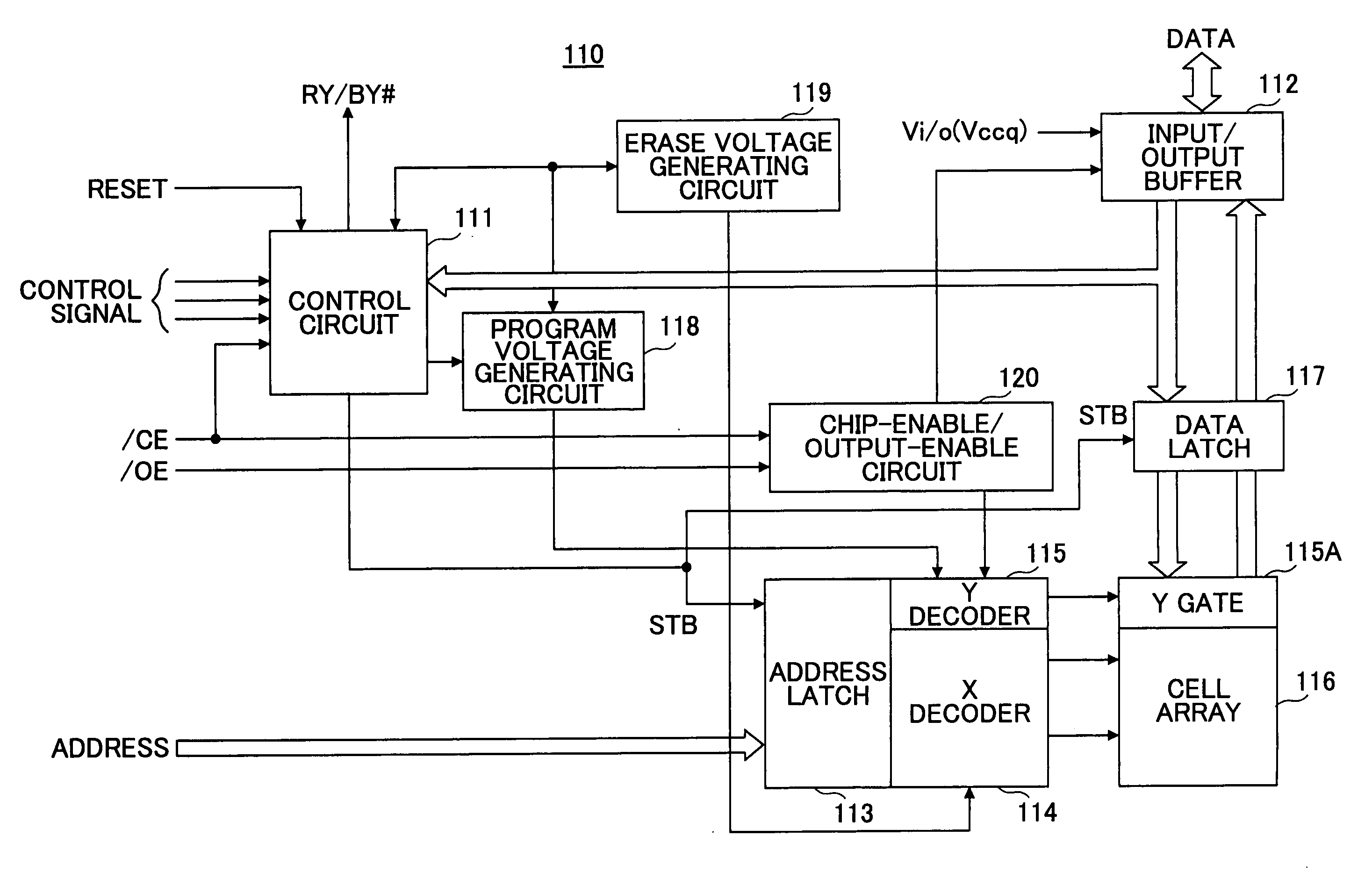
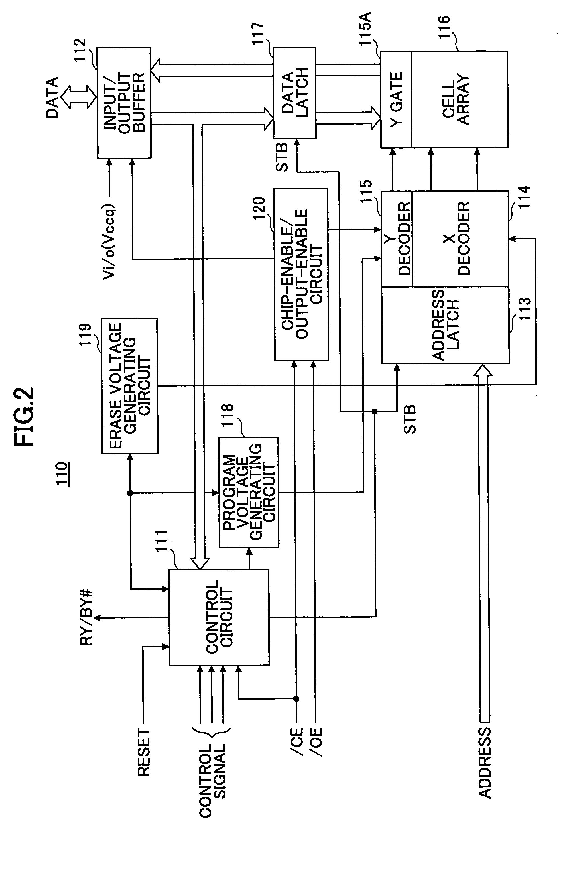
[0030]FIG. 2 is a drawing showing the construction of a nonvolatile semiconductor memory device to which the present invention is applied.

[0031] A nonvolatile semiconductor memory device 110 of FIG. 2 includes a control circuit 111, an input / output buffer 112, an address latch 113, an X decoder 114, a Y decoder 115, a Y gate 115A, a cell array 116, a data latch 117, a program voltage generating circuit 118, an erase voltage generating circuit 119, and a chip-enable / output-enable circuit 120.

[0032] The control circuit 111 receives control signals from an exterior, and operates as a state machine based on the control signals, thereby controlling individual units of the nonvolatile semiconductor memory device 110.

[0033] The input / output buffer 112 receives data from the exterior, and supplies the data to the data latch 117. The address latch 113 receives and l...


PUM


Abstract

A nonvolatile semiconductor memory device includes nonvolatile memory cells each configured to store 2-bit information per memory cell, and a control circuit configured to verify with a first threshold one or more bits subjected to writing of new data and to verify with a second threshold one or more bits subjected to refreshing of existing data in a program operation that performs the writing of new data and the refreshing of existing data simultaneously with respect to the nonvolatile memory cells, the second threshold being lower than the first threshold.

Description

CROSS-REFERENCE TO RELATED APPLICATION [0001] This is a continuation of International Application No. PCT / JP2003 / 005457, filed on Apr. 28, 2003, the entire contents of which are hereby incorporated by reference.BACKGROUND OF THE INVENTION [0002] 1. Field of the Invention [0003] The present invention generally relates to nonvolatile semiconductor memory devices, and particularly relates to a programming circuit and programming method for use in a nonvolatile semiconductor memory device. [0004] 2. Description of the Related Art [0005] In general, nonvolatile semiconductor memory devices such as flash memories use a current flowing through a reference cell having a predetermined threshold as a reference current, and compare a drain current of a memory cell read at the time of read operation with the reference current. Determination as to whether the data is “1” or “0” varies depending on whether the drain current of the read memory cell is greater than the reference current. [0006] As ...

Claims


Application Information

Patent Timeline
Patent Type & Authority Applications(United States)
IPC IPC(8): G11C16/06G11C16/10G11C16/28G11C16/34
CPCG11C16/10G11C16/28G11C16/3454G11C16/3431G11C16/3418
Inventor KURIHARA, KAZUHIRO
Owner FUJITSU LTD
Why Eureka
Try Eureka