Electric motor and method of driving the same

a technology of electric motor and electric motor, which is applied in the direction of gearing, magnetic circuit rotating parts, magnetic circuit shape/form/construction, etc., can solve the problems of electric motor stopping, difficult to appropriately control the phase difference between the first and second rotors solely by centrifugal for

Inactive Publication Date: 2007-06-07
HONDA MOTOR CO LTD
View PDF5 Cites 23 Cited by
  • Summary
  • Abstract
  • Description
  • Claims
  • Application Information

AI Technical Summary

Benefits of technology

[0036] According to the above described method of driving an electric motor, if, for example, a command to execute weak field control in accordance with the rotational speed and power supply voltage or the like of the electric motor is output from an external control unit or the like, then the first planetary carrier is pivoted around the axis of rotation such that the electric motor changes to a weak field state in which the permanent magnets of the inner circumferential side rotor and the permanent magnets of the outer circumferential side rotor are positioned with the same magnetic pole facing each other. Accordingly, it is possible to prevent a high voltage device such as, for example, an inverter that controls the supply of power to the stator coil being placed in an over-voltage state.

Problems solved by technology

In an electric motor according to an example of the above described conventional technology, for example, when the phase difference between the first and second rotors is controlled in accordance, for example, with the rotational speed of the electric motor, then it is only possible to control the phase difference between the first and second rotors when the electric motor is in operation, namely, when a centrifugal force corresponding to the rotational speed is in action, and the problem arises that it is not possible to control the phase difference at a suitable timing that includes when the electric motor is stopped.
Moreover, in a state in which external vibration can easily affect the electric motor, such as when the electric motor is mounted as a driving source in a vehicle, then the further problem arises that it is difficult to appropriately control the phase difference between the first and second rotors solely by the action of centrifugal force.
Furthermore, in this case, because the phase difference is controlled irrespective of variations in the power supply voltage of the power supply for the motor, there is a possibility, for example, that a failure will occur such as the size relationship between the power supply voltage and the counter-electromotive force of the electric motor becoming reversed.
In addition, if, for example, the phase difference between the first and second rotors is controlled in accordance with the speed of the rotating magnetic field that is generated in the stator, then because the speed of the rotating magnetic field is altered, the problem arises that processing to control the electric motor becomes extremely complex.

Method used


Image

  • Electric motor and method of driving the same
  • Electric motor and method of driving the same
  • Electric motor and method of driving the same

Examples


Embodiment Construction

[0065] An embodiment of an electric motor and a method of driving an electric motor of the present invention will now be described with reference to the attached drawings.

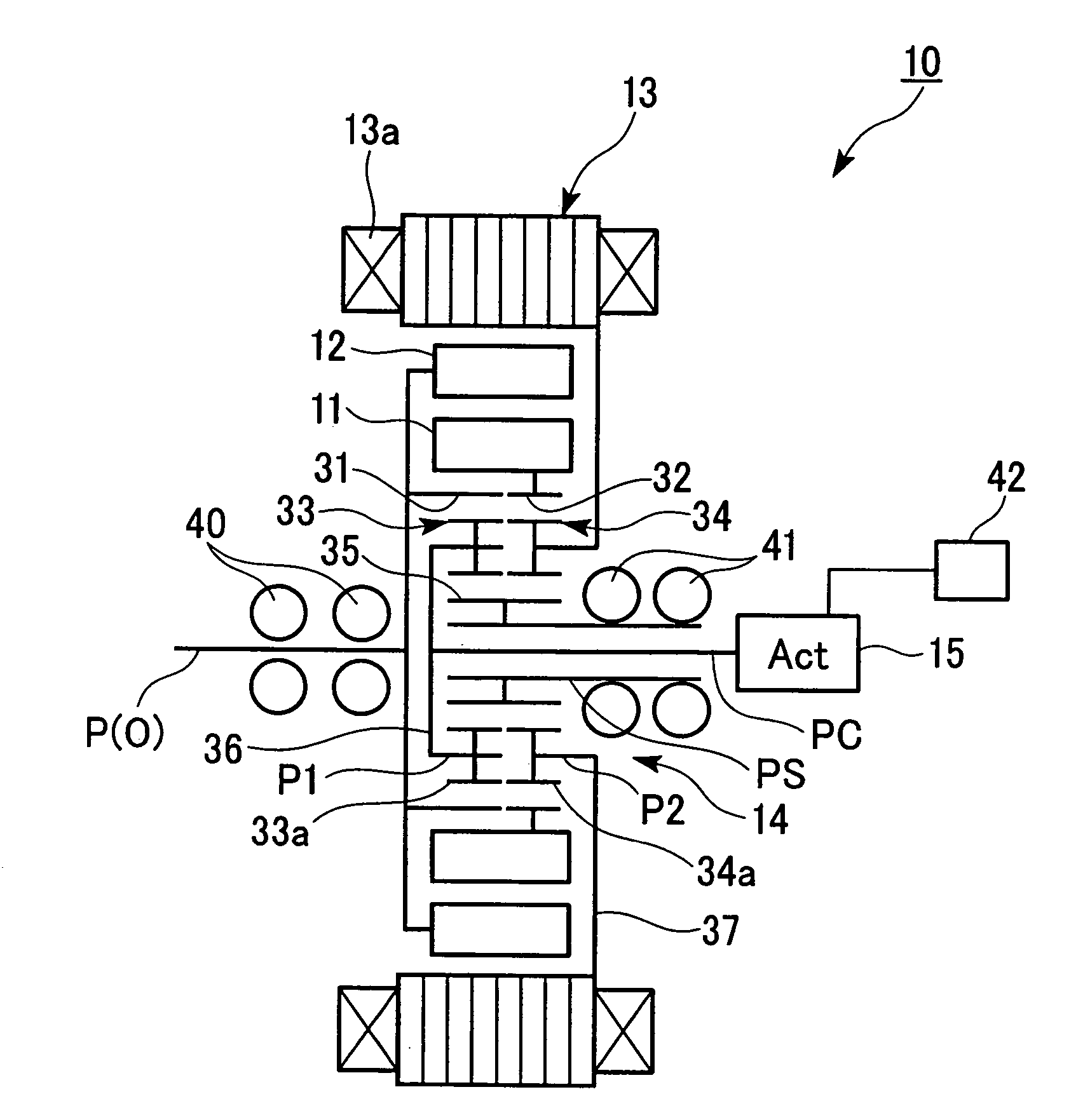
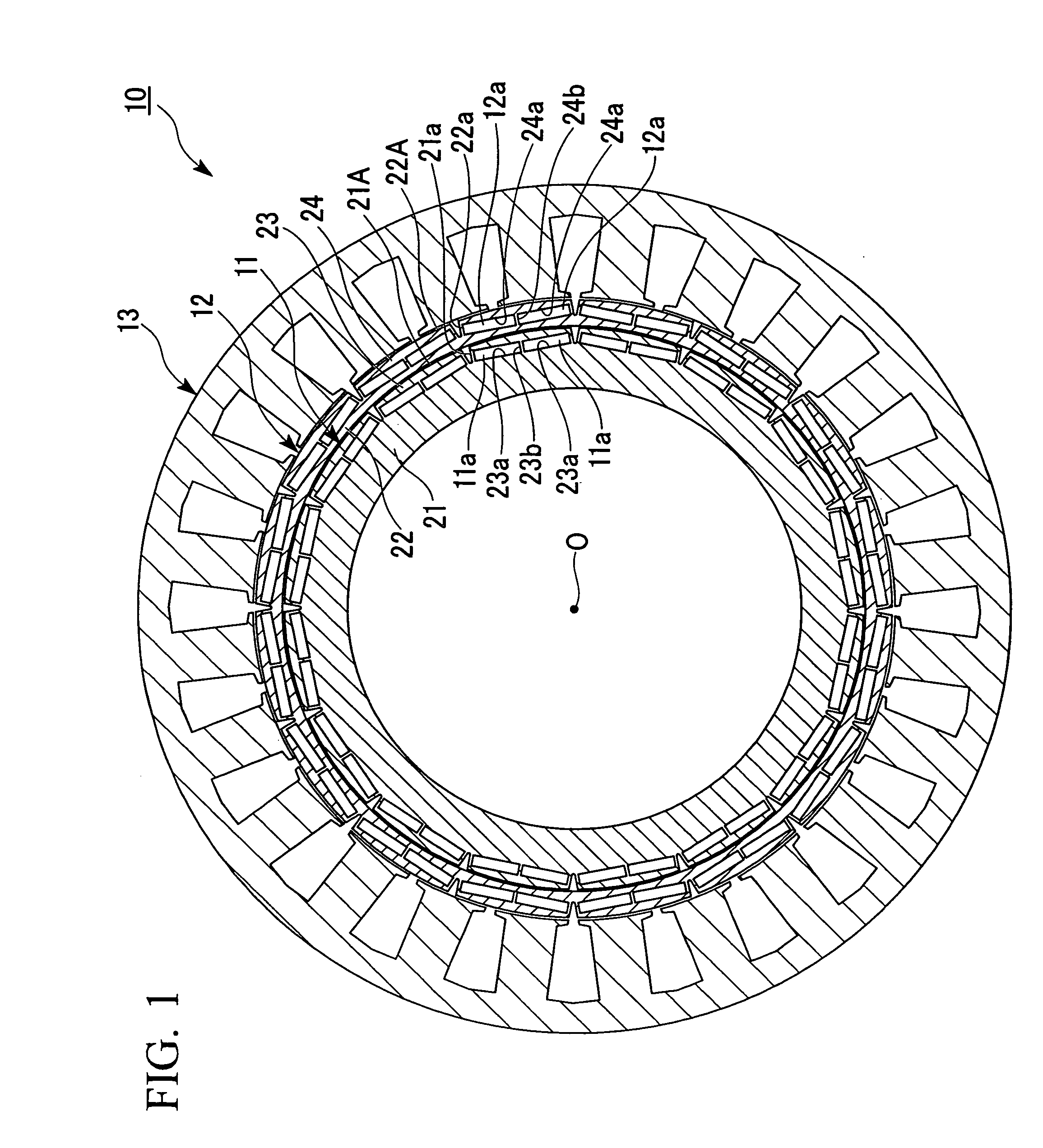
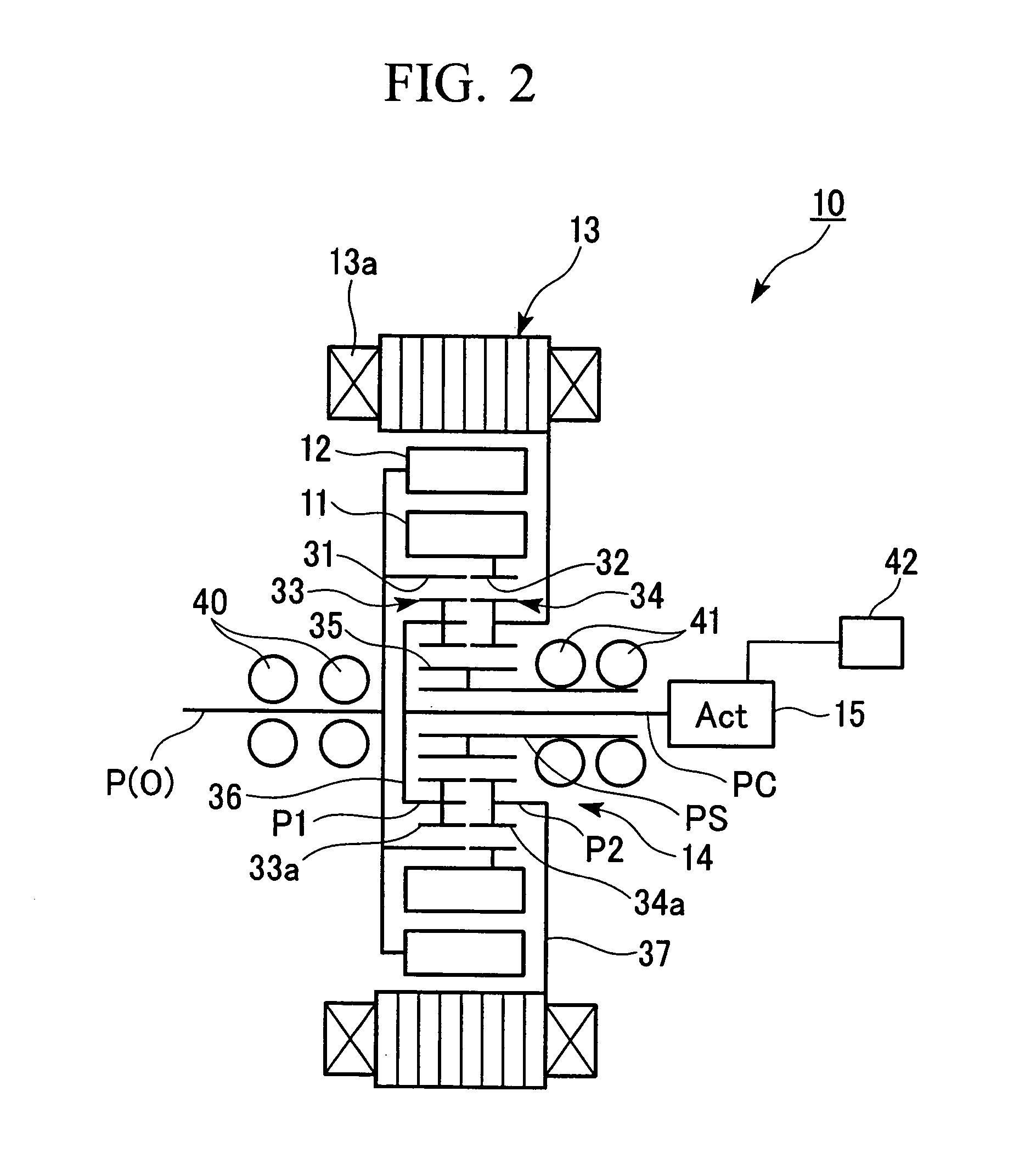
[0066] As is shown in FIGS. 1 and 2, for example, an electric motor 10 according to the present embodiment is a brushless DC motor that is provided with a substantially toroidal inner circumferential side rotor (hereinafter, inner rotor) 11 that is equipped with permanent magnets 11a that are lined up in a circumferential direction, a substantially toroidal outer circumferential side rotor (hereinafter, outer rotor) 12 that is equipped with permanent magnets 12a that are lined up in a circumferential direction, a stator 13 that has a plurality of phases of stator coil 13a that generate a rotating magnetic field causing the inner rotor 11 and the outer rotor 12 to rotate, a planetary gear mechanism 14 that is connected to the inner rotor 11 and the outer rotor 12, and an actuator 15 that sets relative phases betwee...


PUM


Abstract

This electric motor of the present invention is formed by an inner circumferential side rotor, an outer circumferential side rotor, and a planetary gear mechanism that are placed coaxially. The planetary gear mechanism is a single pinion type that includes a first planetary gear train and a second planetary gear train that are each single gear train. A first planetary carrier that supports the first planetary gear train is able to pivot around an axis of rotation, and a second planetary carrier that supports the second planetary gear train is fixed to a stator. The electric motor is further provided with an actuator that pivots the first planetary carrier by a predetermined pivot amount around the axis of rotation.

Description

BACKGROUND OF THE INVENTION [0001] 1. Field of the Invention [0002] The present invention relates to an electric motor and to a method of driving an electric motor. [0003] Priority is claimed on Japanese Patent Application No. 2005-348981, filed Dec. 2, 2005, the contents of which are incorporated herein by reference. [0004] 2. Description of Related Art [0005] Conventionally, an electric motor is known in which there are provided a first and second rotors that are provided concentrically around an axis of rotation of an electric motor, and the relative positions in the circumferential direction of the first and second rotors, namely, the phase difference thereof are controlled in accordance with the rotational speed of the electric motor, or in accordance with the speed of a rotating magnetic field that is generated in a stator (see, for example, Japanese Patent Application, First Publication No. 2002-204541). [0006] In this electric motor, when the phase difference between the fir...

Claims


Application Information

Patent Timeline
Patent Type & Authority Applications(United States)
IPC IPC(8): F16H3/72H02K1/22H02K7/116H02K16/02H02K21/14H02P6/06H02P6/08
CPCH02K7/116H02K16/02H02K21/029
Inventor ATARASHI, HIROFUMI
Owner HONDA MOTOR CO LTD
Why Eureka
Try Eureka