Wireless resource monitoring system and method

a resource monitoring and wireless technology, applied in the field of wireless communications, can solve the problems of proprietary and complex single-purpose hardware and software, inability to measure and report the location of resources in the facility, and the cost or complexity of wireless monitoring systems such as radio frequency identification systems, which are too expensive or too complicated for many ordinary applications,

Inactive Publication Date: 2007-12-20
INNERWIRELESS
View PDF20 Cites 108 Cited by
  • Summary
  • Abstract
  • Description
  • Claims
  • Application Information

AI Technical Summary

Benefits of technology

[0009] A beacon signal is transmitted by the beacons, which includes the identity of the transmitting beacons. The tag receives the beacon signals and measures the signal strength of the beacon signals. The tag then transmits a tag signal, which includes the identity of the transmitting tag, the measured signal strengths of the beacon signals and the identity of the corresponding beacons. The master radio receives the tag signal and forwards the information in the signal to a processor. The beacon-to-tag distances are determined from the measured signal strength values. The locations of the beacons are determined from the beacons' identity. The location of the tag is then determined from the beacon-to-tag distances and the location of the corresponding beacons.
[0010] The beacon signal having the highest beacon signal strength value and the corresponding beacon are identified. The highest beacon signal strength value is compared to a predetermined first threshold value. If the highest beacon signal strength value is greater than the predetermined first threshold value, the location of the tag is indicated in relation to the beacon corresponding to the highest beacon signal strength value. Next, the region which includes the beacon corresponding to the highest beacon signal strength value is identified, and the location of the tag is indicated by the region in which the beacon corresponding to the highest beacon signal strength value is located.
[0011] If there are a minimum number of measured beacon signal strength values from a contiguous group of beacons having values greater than a second threshold value, the tag's location is calculated using the minimum number of measured beacon signal strength values from the contiguous group of beacons having values greater than the second threshold value. If the measured beacon signal strength values are not from a contiguous group of beacons, the tag's location and an uncertainty value associated with the tag's location are calculated and are displayed. If there is not a minimum number of beacon signal strength values greater than a second threshold value, the tag's location is calculated using the beacon signal strength values adjusted by a weighting factor and an uncertainty value associated with the tag's calculated location is calculated.

Problems solved by technology

Presently available wireless systems for monitoring resources, such as Radio Frequency Identification (RFID) systems, are too expensive or too complicated for many ordinary applications.
Also, these RFID systems do not measure and report the location of resources throughout a facility.
Many presently available RFID systems use proprietary and complex single purpose hardware and software.
The WLAN standards do not address the problems associated with proprietary RFID systems, other than to provide their own complex multipurpose protocols.
The WLAN standards leave in place all of the typical system elements and the cost associated with their purchase, installation, and ongoing operation.
The cost of wired connections to the location transceivers, in this case “access points,” often becomes the dominant economic factor and the complexity of the protocol drives the cost of the tags.
Also, since WLAN standards provide a finite maximum communications capacity, the increase in load on this limited communications capacity of the WLAN, as required by typical RFID location systems, increases the complexity of the compromises associated with using the WLAN as the basis for the RFID system.
Consequently, attempts to develop an economically viable system for resource monitoring have proven to be difficult.

Method used


Image

  • Wireless resource monitoring system and method
  • Wireless resource monitoring system and method
  • Wireless resource monitoring system and method

Examples


Embodiment Construction

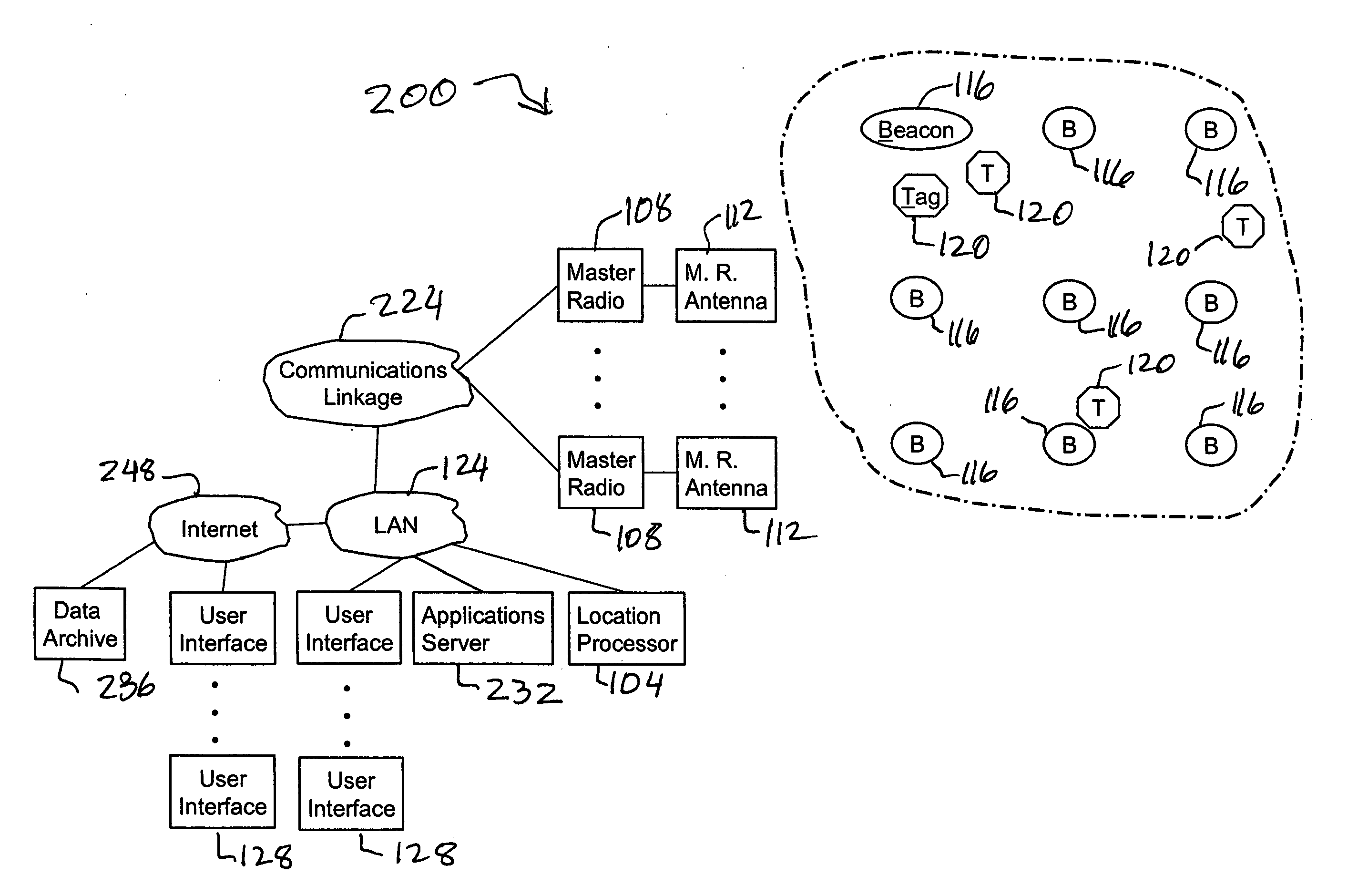
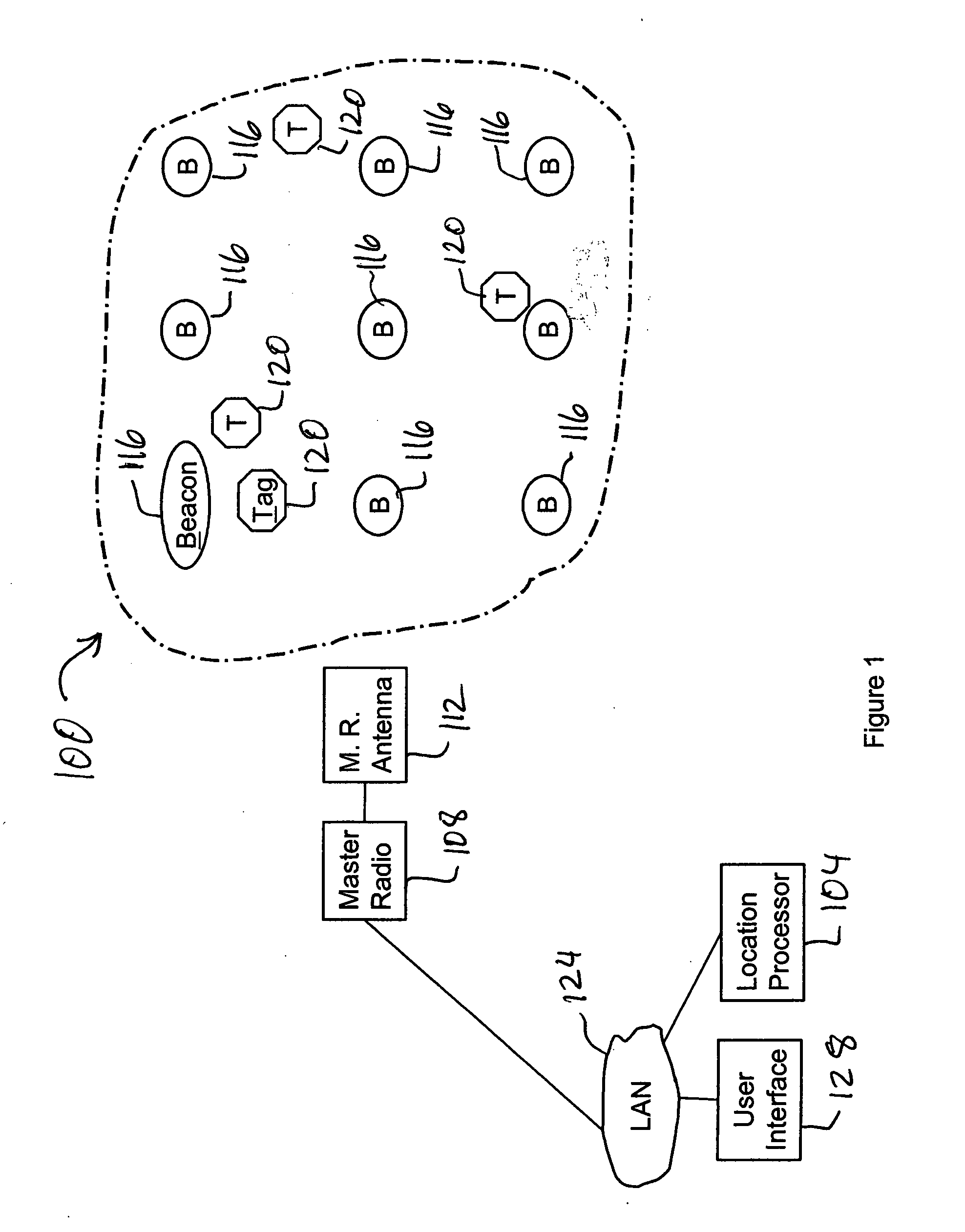
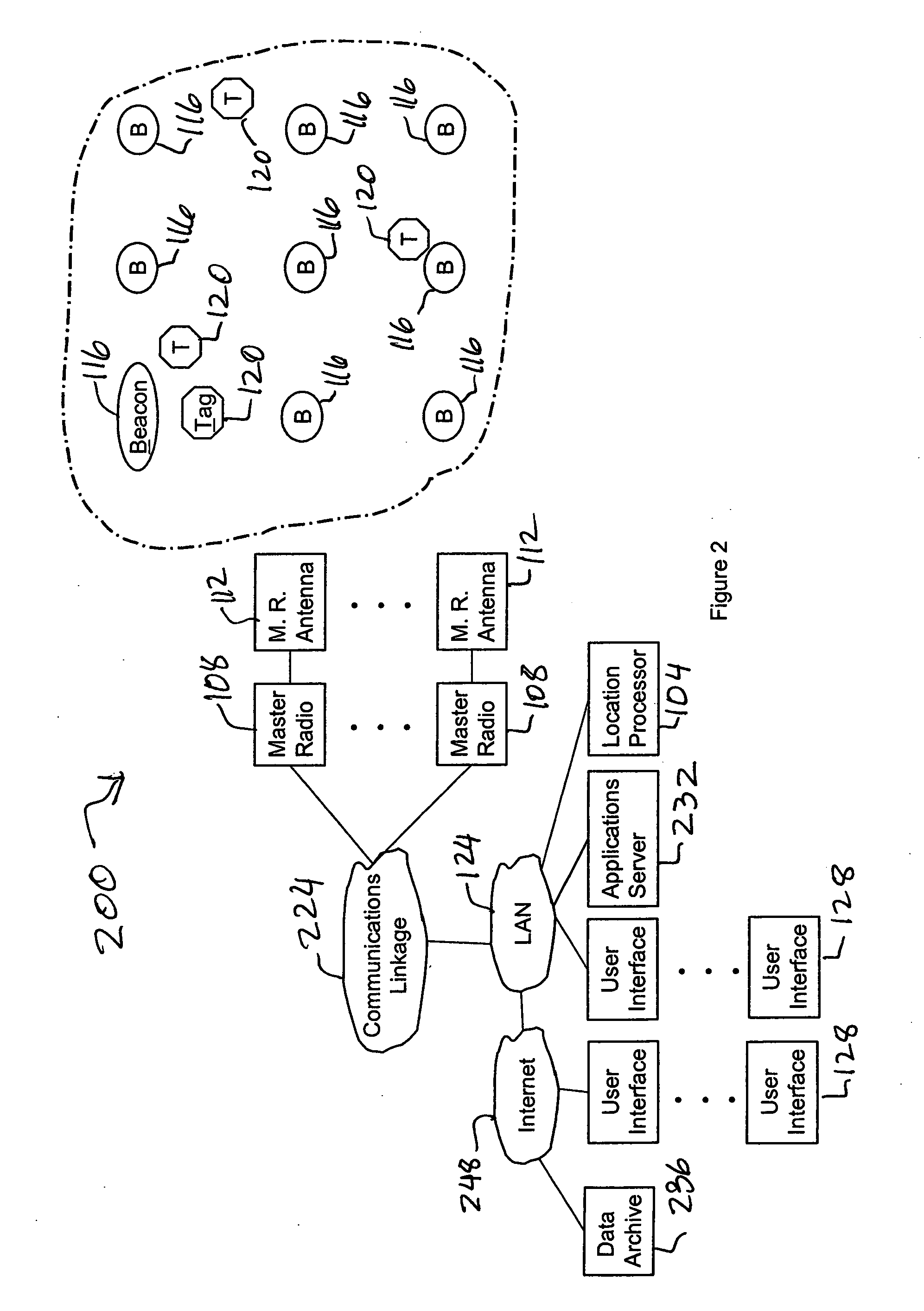
[0018] A wireless resource monitoring system and method provides a solution to the problems associated with existing RFID systems. In one embodiment, the wireless resource monitoring system is a radio frequency (RF) resource monitoring system and method. The wireless resource monitoring system and method may be used in many applications such as, for example, resource tracking, asset inventory, resource recovery, and personnel, staff, visitor, and resource management, and can be deployed in a building, a warehouse, or in any other desired location.

[0019] In one embodiment, the wireless resource monitoring system and method overcomes the disadvantages associated with using proprietary hardware, software, and protocols by building upon the public communications standard known as the IEEE 802.15.4 standard. The IEEE 802.15.14 standard provides a basis for multi-industry use of common hardware (e.g., silicon chip sets for radios) as well as lower levels of common software and protocols ...


PUM


Abstract

A wireless resource monitoring system and method utilizes a network of deployed radio elements including at least one master radio, a plurality of beacons, and at least one tag. The beacons are placed at known positions. The master radio, the beacons and the tag are in wireless communication with each other. The tag is attached to the resource that is being monitored. A beacon signal is transmitted by the beacons, which includes the identity of the transmitting beacons. The tag receives the beacon signals and measures the signal strength of the beacon signals. The tag then transmits a tag signal, which includes the identity of the transmitting tag, the measured signal strengths of the beacon signals and the identity of the corresponding beacons. The location of the tag is then determined from the tag signal.

Description

BACKGROUND OF THE INVENTION [0001] 1. Field of the Invention [0002] The invention relates generally to the field of wireless communications. More specifically, the invention relates to a wireless resource monitoring system and method. The invention utilizes a network of deployed radio elements such as master radios, beacons and tags to monitor the location of resources. [0003] 2. Description of the Related Art [0004] Presently available wireless systems for monitoring resources, such as Radio Frequency Identification (RFID) systems, are too expensive or too complicated for many ordinary applications. Also, these RFID systems do not measure and report the location of resources throughout a facility. In many applications such as, for example, residential, commercial, and industrial building automation, simple and inexpensive systems are desired. [0005] Many presently available RFID systems use proprietary and complex single purpose hardware and software. Also, RFID systems typically u...

Claims


Application Information

Patent Timeline
Patent Type & Authority Applications(United States)
IPC IPC(8): G01S3/02H04B1/38
CPCG06Q10/087G08B13/2462G01S5/0036G01S5/14G01S5/013G01S5/0244G01S5/0295
Inventor MCCOY, JAMES WILLIAM
Owner INNERWIRELESS
Why Eureka
Try Eureka