
Device For Automatically Measuring Characteristics Of An Ophthalmic Lens

a technology of automatically measuring characteristics and ophthalmic lenses, which is applied in the direction of measurement devices, instruments, structural/machine measurement, etc., can solve the problem of insufficient accuracy of measurements taken, and achieve the effect of improving the accuracy of measurements

Active Publication Date: 2007-12-20
ESSILOR INT CIE GEN DOPTIQUE
View PDF1 Cites 16 Cited by
  • Summary
  • Abstract
  • Description
  • Claims
  • Application Information

AI Technical Summary

Benefits of technology

[0010] An object of the present invention is to provide a device that makes it possible to make multiple measurements of different types and to do so with all types of eyeglass lenses, while also improving the accuracy of the measurements taken.
[0017] It is thus possible to cause the device to adopt various engagement and / or disengagement states of the two beam separator masks, in order to make specific measurements in each of said states. In the description below it can be seen that each state corresponding to activation of the mask downstream or upstream relative to the lens (in configurations known as the “conventional Hartmann” or “inverse Hartmann”) provides better performance for certain types of measurements than does the other state. In addition, it is possible to combine the results of the measurements performed in succession in different states in order to achieve an overall measurement that is more accurate than it would have been if performed in one state only.

Problems solved by technology

A drawback of that device lies in the fact that since the Hartmann matrix is situated beside the front face of the lens, i.e. in a so-called “inverted” Hartmann configuration, the measurements taken can be insufficiently accurate, in particular when measuring optical powers of the lens or centering and / or axis characteristics.

Method used


Image

  • Device For Automatically Measuring Characteristics Of An Ophthalmic Lens
  • Device For Automatically Measuring Characteristics Of An Ophthalmic Lens
  • Device For Automatically Measuring Characteristics Of An Ophthalmic Lens

Examples


Embodiment Construction

[0028] The following description with reference to the accompanying drawings of an embodiment given by way of non-limiting example makes it possible to understand clearly what the invention consists in and how it can be implemented.

[0029] In the accompanying drawings:

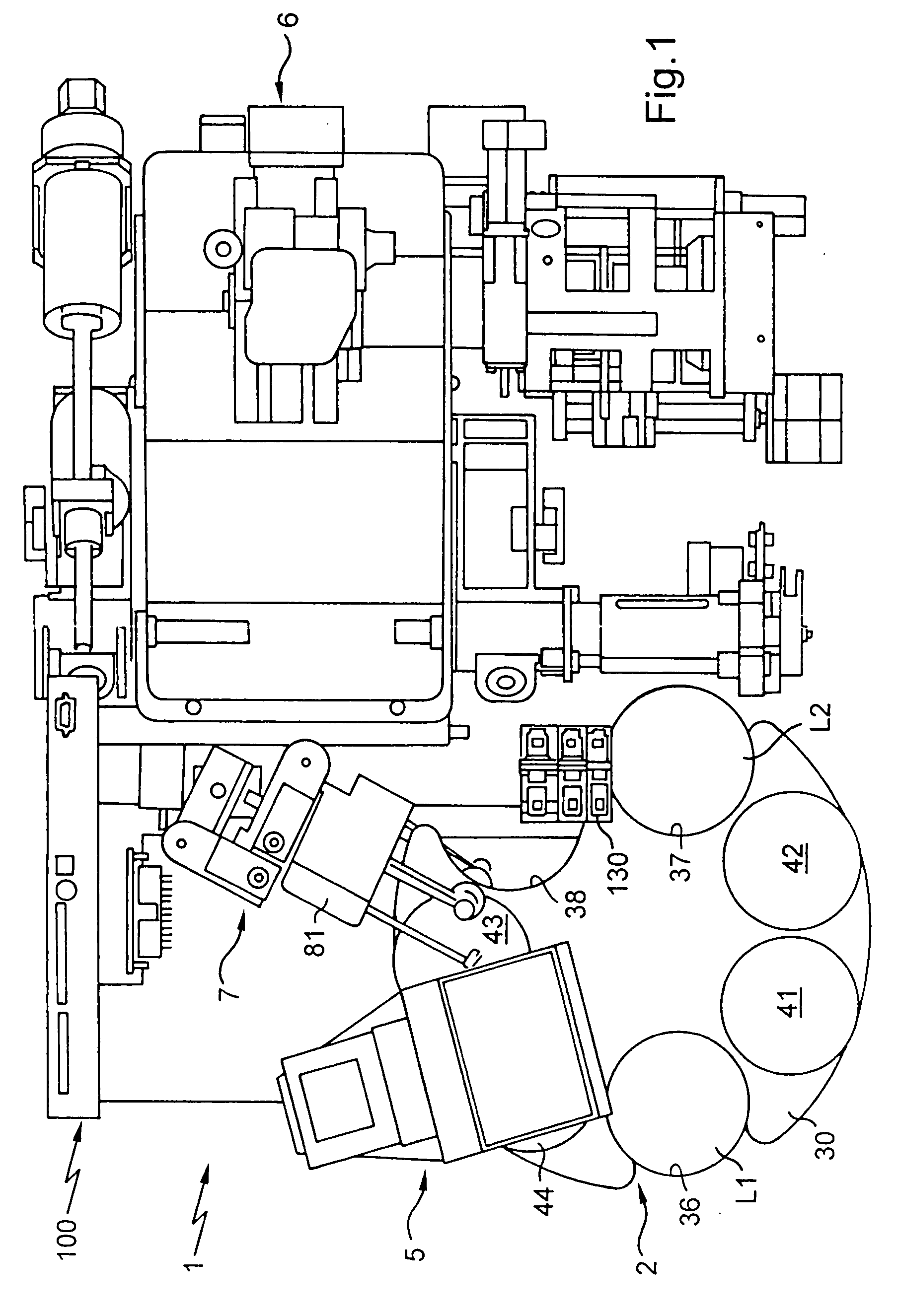
[0030]FIG. 1 is a diagrammatic plan view of the device of the present invention for automatically preparing ophthalmic lenses for mounting;

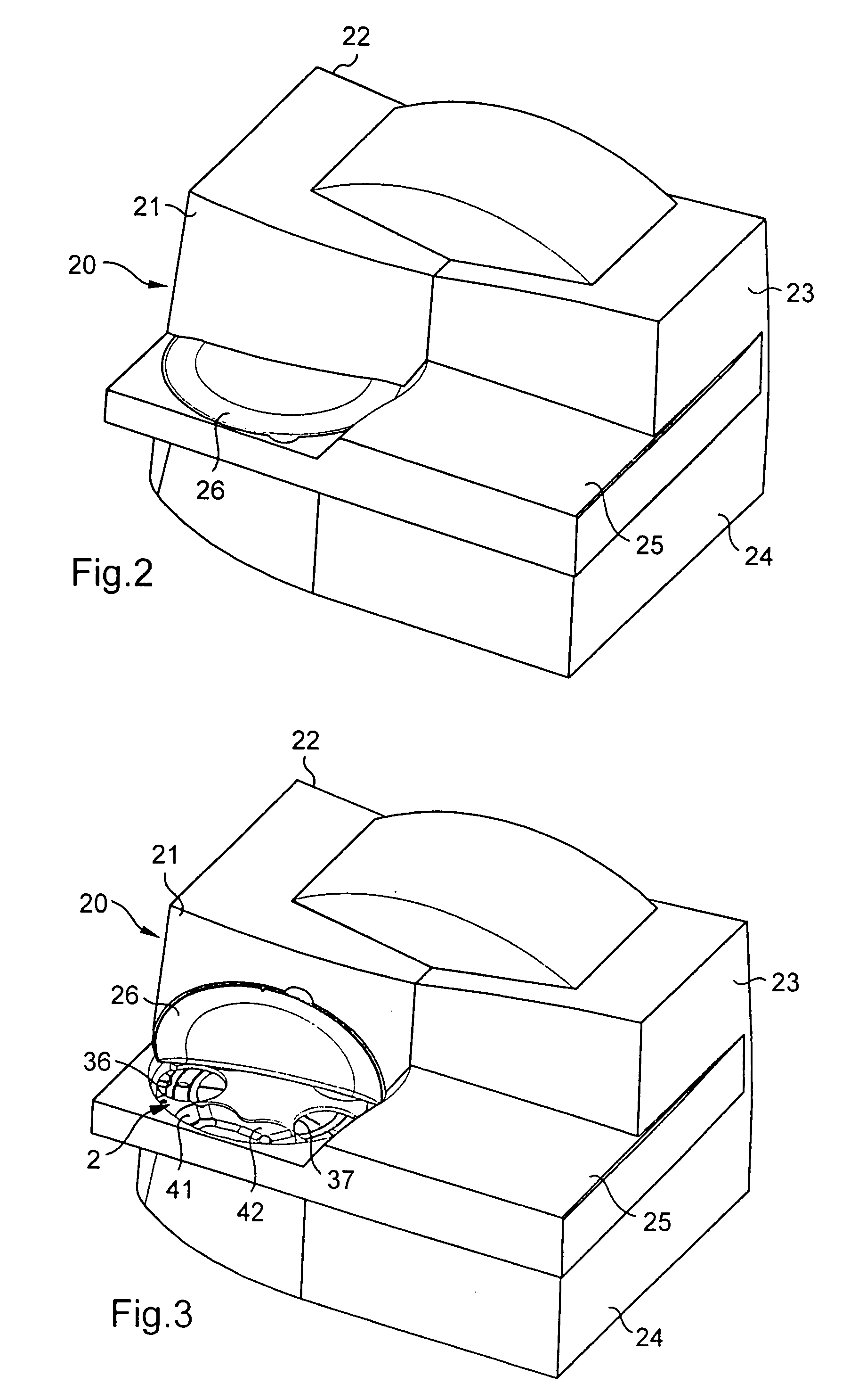
[0031]FIG. 2 is an overall perspective view of the outside of the automatic preparation device fitted with a cover;

[0032]FIG. 3 is a view similar to FIG. 2, with an access door of the cover shown open for loading lenses that are to be prepared onto reception and first and second transfer means, and for unloading lenses therefrom;

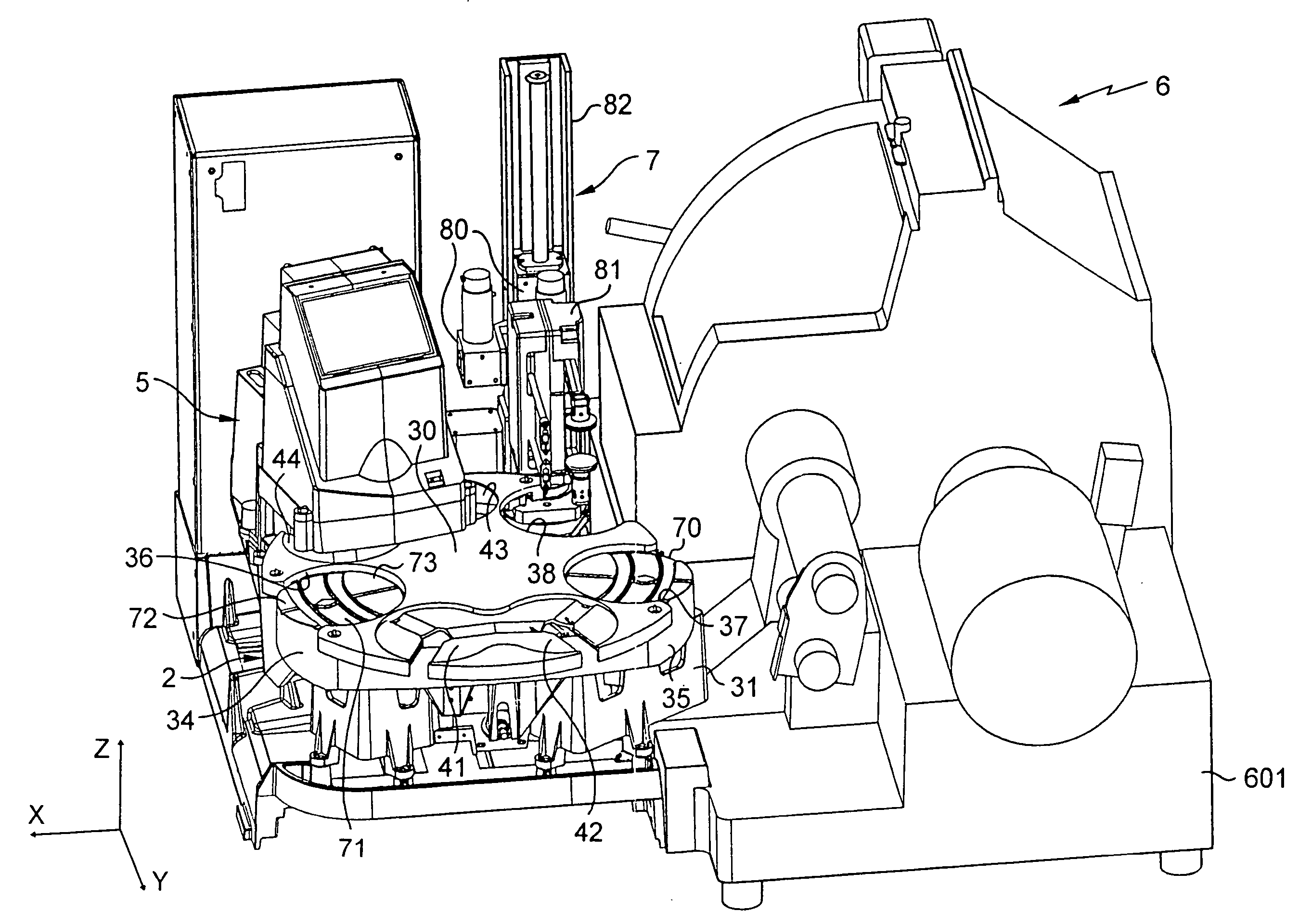
[0033]FIG. 4 is a perspective view of the inside of the automatic preparation device;

[0034]FIG. 5 is a perspective view of the carousel and the seats forming the reception and first and second transfer means;

[0035]FIG. 6 is a perspective view of a port...


PUM


Abstract

A device for automatically measuring characteristics of an ophthalmic lens (L1), includes: a support (2) designed to receive such a lens; on one first side of the lens support, illuminating elements (208) including an optical system for producing a light beam directed towards the ophthalmic lens mounted on the support; and on a second side of the support, elements for analyzing (210) the image transmitted by the ophthalmic lens mounted on the support and illuminated by the illuminating elements (208); elements for splitting the light beam including a first mask (220) forming a Hartmann array and arranged on the first side of the lens support to be illuminated, upstream of the lens by the light beam.

Description

TECHNICAL FIELD TO WHICH THE INVENTION RELATES [0001] The present invention relates in general to mounting ophthalmic lenses of a pair of correcting eyeglasses in a frame, and it relates more particularly to a device for automatically measuring characteristics of an ophthalmic lens and suitable for being integrated in an automatic device for preparing the lenses of a pair of eyeglasses for mounting in the frame selected by the user. TECHNOLOGICAL BACKGROUND [0002] The technical portion of the work carried out by an optician consists in mounting a pair of ophthalmic lenses in or on the frame selected by the user, in such a manner that each lens is suitably positioned facing the corresponding eye of the user so as to perform as well as possible the optical function for which it is designed. In order to do this, it is necessary to perform a certain number of operations. [0003] After the frame has been selected, the optician must begin by situating the position of the pupil of each eye ...

Claims


Application Information

Patent Timeline
Patent Type & Authority Applications(United States)
IPC IPC(8): G01M11/02
CPCG01M11/0235G01M11/02G01M11/00
Inventor DIVO, FABIEN
Owner ESSILOR INT CIE GEN DOPTIQUE
Learn More