Apparatus and method for scalable power distribution

a power distribution and applicator technology, applied in the direction of connection contact material, circuit-breaking switch, coupling device connection, etc., can solve the problem that the system cannot be scalable, the circuit the corresponding circuit breakers cannot be configured for the correct size or quantity of the circuit, and the system may not be scalable. to achieve the effect of safe installation and removal

Active Publication Date: 2007-12-20
AMERICA POWER CONVERSION CORP
View PDF81 Cites 84 Cited by
  • Summary
  • Abstract
  • Description
  • Claims
  • Application Information

AI Technical Summary

Benefits of technology

[0010] In one or more embodiments, the invention provides a modular, scalable power distribution system that provides plug-in modules that may be safely installed and removed without disrupting other electrical circuits connected to the power distribution unit. As a result, in some embodiments, the invention provides for a scalable power distribution apparatus that provides flexibility to meet the changing electrical needs of a facility such as a data center. In still other embodiments, the invention provides a system with a limited set of components that may be universally applied to a wide variety of applications.

Problems solved by technology

Problems with these approaches include the fact that the installation or removal of a circuit breaker from the panel board or power distribution unit requires that a skilled individual (i.e., an electrician) perform the installation or removal in close proximity to energized electrical circuits which may include exposed electrical connections and / or conductors.
Of course, given the critical nature of the electrical load in the data centers, even these scheduled outages are undesirable.
In addition, such systems may not be scalable, that is, each panel board or other power distribution unit may not be configured for the correct size or quantity of circuits and corresponding circuit breakers.
Given the dynamic nature of the electrical load that may be included in the data center, for example, the addition of one or more computers, servers, chillers, etc., the preceding approach does not provide an advantage except in the rare instance where the power distribution unit supplies a known, fixed electrical load.
That is, the preceding approach is only effective where the designer and / or user of the distribution system can accurately identify the electrical loading and power distribution requirements of the facility at the time of installation.
Generally, it is unrealistic to expect that the designer and / or user will accurately predict the electrical loading (e.g., the quantity of distribution circuits and their maximum loading) given the dynamic nature of facility design, power distribution systems and the connected electrical load.

Method used


Image

  • Apparatus and method for scalable power distribution
  • Apparatus and method for scalable power distribution
  • Apparatus and method for scalable power distribution

Examples


Embodiment Construction

[0035] This invention is not limited in its application to the details of construction and the arrangement of components set forth in the following description or illustrated in the drawings. The invention is capable of other embodiments and of being practiced or of being carried out in various ways. Also, the phraseology and terminology used herein is for the purpose of description and should not be regarded as limiting. The use of “including,”“comprising,” or “having,”“containing”, “involving”, and variations thereof herein, is meant to encompass the items listed thereafter and equivalents thereof as well as additional items.

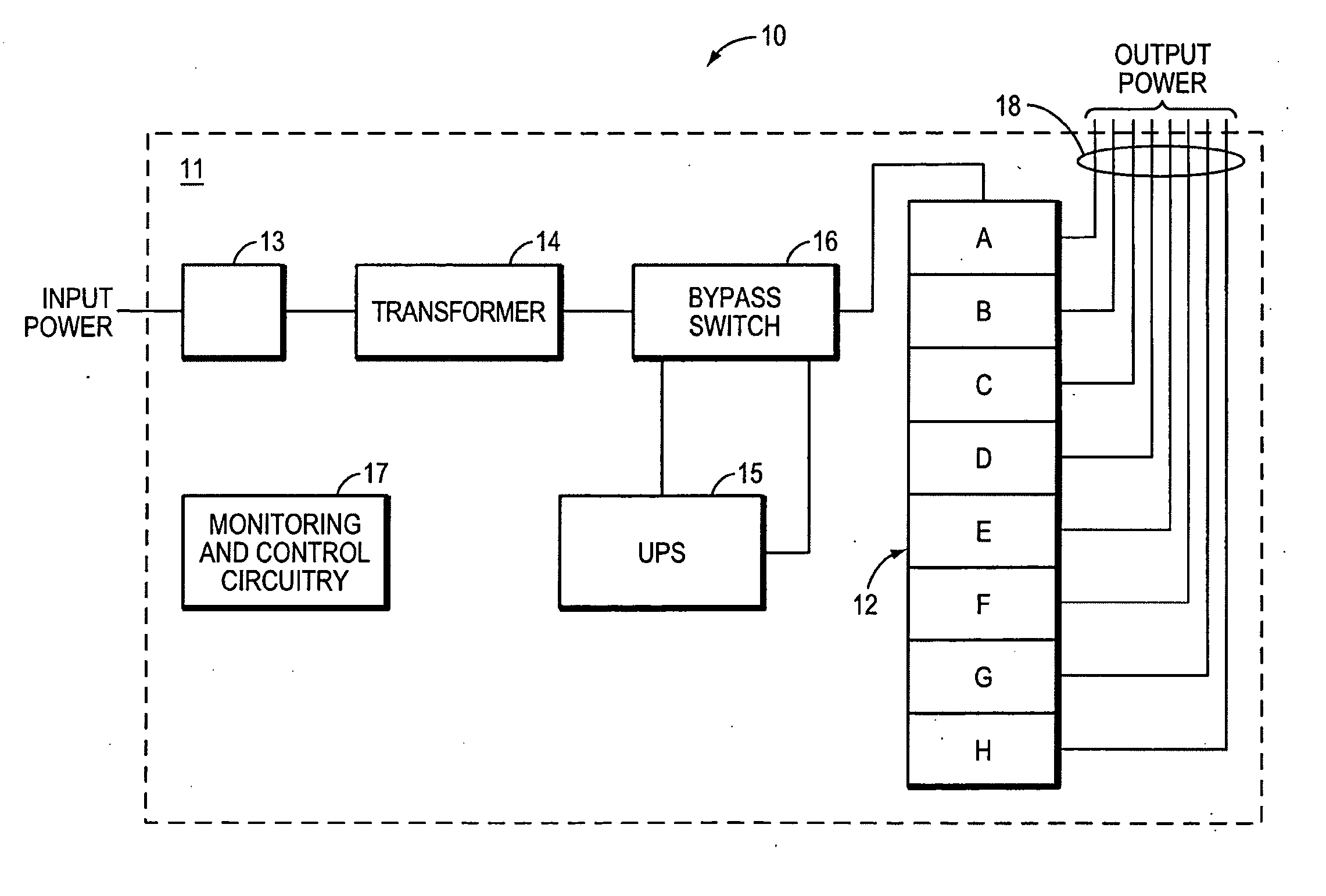
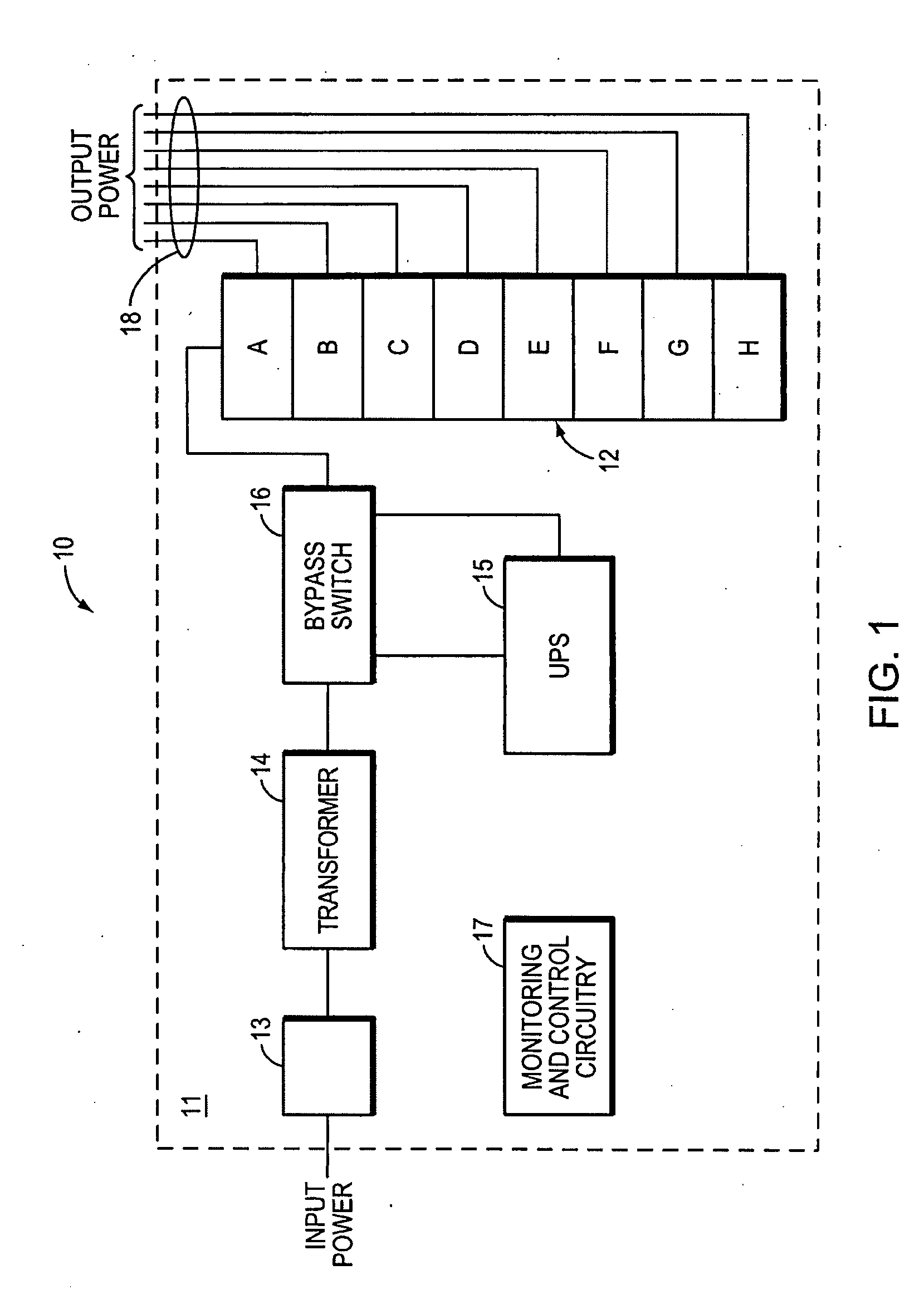
[0036]FIG. 1 illustrates a power distribution system 10 in accordance with one embodiment, where the system includes a power distribution unit 11 (“PDU”) that provides a plurality of output circuits 18 (e.g., branch circuits) to supply electrical power to a plurality of electrical loads, for example, loads found in a data center or another type of facility. T...


PUM


Abstract

According to one aspect of the invention, a plug-in module is provided for installing in a power distribution assembly. In one embodiment, the plug-in module may include an overcurrent protection device, a power cable, which may include a first end coupled to the overcurrent protection device, and a second end coupled to the first end, one or more receptacle outlets attached to the second end and electrical contacts coupled to the overcurrent protection device and configured to couple the plug-in module to a plurality of stationary electrical conductors of the power distribution assembly.

Description

RELATED APPLICATIONS [0001] The present application is a continuation-in-part of and also claims priority under 35 U.S.C. §120 to co-pending U.S. patent application Ser. No. 11 / 455,227, filed Jun. 16, 2006, entitled APPARATUS AND METHOD FOR SCALABLE POWER DISTRIBUTION which is incorporated herein by reference in its entirety.BACKGROUND OF INVENTION [0002] 1. Field of Invention [0003] Embodiments of the invention relate generally to electrical power distribution equipment. More specifically, at least one embodiment relates to an apparatus and a method for scalable power distribution. [0004] 2. Discussion of Related Art [0005] Centralized data centers for computer, communications and other electronic equipment have been in use for a number of years. More recently, with the increasing use of the Internet, large scale data centers that provide hosting services for Internet service providers (“ISPs”), application service providers (“ASPs”) and Internet content providers are becoming incr...

Claims


Application Information

Patent Timeline
Patent Type & Authority Applications(United States)
IPC IPC(8): H02H3/08H01R13/66
CPCH01R25/003H01R13/6666
Inventor SPITAELS, JAMESZIEGLER, WILLIAM
Owner AMERICA POWER CONVERSION CORP
Why Eureka
Try Eureka